Key Takeaways
- Designations like 600S162-43 encode member size, strength, coating, and assembly behavior in one code
- AISI S240 covers structural framing; S220 covers nonstructural—mixing them creates compliance risk
- Design specs and installed performance diverge due to manufacturing tolerances and field conditions
- Spec correctly by separating nominal vs. actual dimensions and design thickness vs. delivered thickness
What CFS Framing Specifications Represent in Construction
Cold-formed steel framing specifications set the dimensional, material, and performance requirements that engineers design to and contractors buy against. Get the nomenclature or standards references wrong, and you pay for it in field discrepancies, wrong material on site, or rejected submittals.
Specifications operate within a three-level hierarchy:
- Member-level specifications define individual stud or track properties: web depth, flange width, base metal thickness, steel grade, and coating weight
Assembly-level specifications establish wall, floor, or roof system performance: load capacity, deflection limits, fire ratings, STC (acoustic) ratings, and thermal performance
- Project-level specifications invoke codes, standards, and quality requirements: AISI S240-20 for structural framing, S220 for non-structural framing, and IBC/IRC compliance
Specification Components and Their Roles
The standard member designation format encodes critical properties into a compact identifier. For example, 600S162-43 breaks down as:
- 600 = 6.00-inch nominal web depth
- S = C-shaped stud/joist with stiffening lips
- 162 = 1.625-inch flange width
- 43 = 43-mil thickness designation
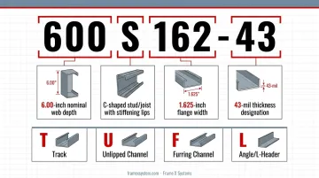
Additional member-type codes include T (track), U (unlipped channel), F (furring channel), and L (angle/L-header).
Material Specifications
Material specs lock in the steel and coating you actually receive on site:
- Steel grade: ASTM A1003 Structural Grade 33 Type H or Grade 50 Type H, with yield strengths of 33 ksi or 50 ksi
- Coating protection: CP60 minimum (includes ASTM A653 G60 galvanization) for normal exposure; CP90 or higher for severe environments
- Corrosion resistance: ASTM A875 zinc-5% aluminum alloy coatings for coastal or industrial zones
Performance Specifications
Performance specs turn those material properties into system behavior:
- Load capacity per AISI S100 design provisions
- Deflection limits: typically L/360 for floors, L/240 for roofs
- Fire ratings for UL-listed assemblies tied to member sizes and fastener schedules
- Acoustic performance: STC ratings for partition assemblies
- Thermal performance that accounts for steel thermal bridging
Standards References
Standards references form the compliance framework:
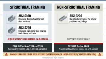
- AISI S100: Structural design of cold-formed steel members
- AISI S240: Structural framing for load-bearing walls, floors, and roofs
- AISI S220: Non-structural framing for interior partitions and ceilings
- 2024 IBC Sections 2204 and 2206: Reference S100-16(2020) w/S2-20, S240-20, and S220-20
- 2024 IRC Section R603: Prescriptive CFS wall framing invoking AISI S240 and S230
Structural framing carries building loads and needs stamped engineering calculations. Non-structural framing supports finishes only.
Each category follows different standards and submittal rules. Mixing them either over-specifies (and wastes money) or under-specifies (and creates safety risk).
Factors That Influence CFS Specifications in Real-World Application
Specifications exist in an ideal design state but must adapt to manufacturing capabilities, installation methods, and environmental conditions. Understanding these factors prevents specification failures that appear only during construction.
Design Intent vs. Manufacturing Capabilities
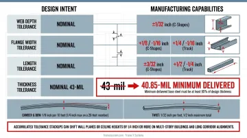
AISI S240-20 Table A5-3 establishes dimensional tolerances that create gaps between nominal and delivered dimensions:
- Web depth tolerance: ±1/32 inch for C-shapes
- Flange width tolerance: +1/8/-1/16 inch for C-shapes; +1/4/-1/16 inch for track
- Length tolerance: ±3/32 inch for C-shapes; +1/2/-1/4 inch for track
- Thickness tolerance: Minimum delivered base steel must be at least 95% of design thickness
This means a 43-mil stud specification requires minimum 40.85-mil delivered thickness, not simply "43 mils minus 5%."
Roll-forming processes create additional variations within acceptable limits:
- Camber and bow: Maximum 1/8 inch per 10 feet (a 20-foot member allows 1/4-inch total)
- Twist: 1/32 inch per foot, 1/2-inch maximum total
- Shape consistency: Flange angles and lip dimensions vary slightly across production runs
These tolerance stackups affect multi-story buildings and long corridor alignments, where accumulated variations can shift wall planes or ceiling heights by 1/4 inch or more.
Field Installation and Assembly Conditions
Connection methods affect assembly performance differently than individual member capacity. Specifications must address:
- Screw placement and spacing: Edge distance, fastener diameter, and spacing intervals determine shear and bearing capacity at joints
- Assembly sequence: Track-to-stud connections, blocking, and bridging affect load transfer and system stability
- Installation tolerances: Plumb, level, and alignment requirements beyond manufacturing tolerances
Environmental factors during construction also affect compliance:
- Temperature variations cause steel thermal expansion (coefficient ≈ 6.5×10⁻⁶ in/in/°F)
- Moisture exposure before enclosure can degrade galvanized coatings if ponding occurs
- Job site storage affects member straightness: improper stacking introduces permanent bow
Even correctly manufactured materials fail specifications if mishandled. Storing studs on uneven ground, exposing bundles to standing water, or dropping members from height introduces damage outside manufacturing tolerances.
Code and Standards Evolution
Building code cycles update every three years, while AISI standards revise independently. The 2024 IBC references AISI S100-16(2020), S240-20, and S220-20. Projects designed under the 2021 IBC used earlier standard editions.
Design documents from different eras can mismatch specified requirements and current code provisions. Local jurisdiction amendments often go further than model codes.
NYC Building Code 2022 Section 1705.2.6 requires special inspection beyond base IBC rules, covering:
- Identification and condition
- Member sizes and layout
- Bearing conditions
- Fastener diameter, length, quantity, spacing, edge distance, and location
- Connectors and bracing
Range of CFS Specifications
CFS specifications operate within defined ranges established by industry standards, manufacturing capabilities, and structural requirements. Understanding these ranges prevents over-specification and costly field changes.
Nominal Dimensions vs. Actual Dimensions
Nominal dimensions are rounded design values used for identification (6-inch stud, 1-5/8-inch flange), while actual dimensions reflect manufactured reality within AISI tolerances. A nominal 6-inch web measures 6.00 inches ±1/32 inch, meaning acceptable delivery ranges from 5.97 to 6.03 inches.
Critical distinction: C-shape web depth measures outside-to-outside, while track inside web depth measures inside-to-inside. Track depth is intentionally oversized (+1/32 to +1/8 inch) to accommodate stud insertion. That difference often confuses specification and ordering. Calling out "6-inch track" without the measurement basis leads to fit problems.
Shop drawings must show actual dimensions with tolerances, not nominal values. In large assemblies, those nominal-to-actual gaps stack up. A 100-foot corridor using 600S studs at 16 inches on-center can shift ±1/4 inch in overall length, enough to affect door frames, window openings, or structural alignments.
Material Thickness: Gauge vs. Mils and Design Thickness
The industry now uses mils (1 mil = 0.001 inch) rather than gauge numbers, which are inconsistent across industries. Common structural thicknesses and their approximate gauge equivalents:
| Mil Designation | Former Gauge | Minimum Base Steel (in.) | Design Thickness (in.) |
|---|---|---|---|
| 33 | 20 | 0.0329 | 0.0346 |
| 43 | 18 | 0.0428 | 0.0451 |
| 54 | 16 | 0.0538 | 0.0566 |
| 68 | 14 | 0.0677 | 0.0713 |
| 97 | 12 | 0.0966 | 0.1017 |
Source: AISI S240-20 Table A5-1
Design thickness accounts for the -5% manufacturing tolerance and is the value used in structural calculations. A 43-mil member has 0.0451-inch design thickness, not 0.0430 inch. Using nominal thickness in calculations underestimates capacity and creates unsafe designs.
Allowable Tolerance and Boundary Limits
AISI dimensional tolerances establish the acceptable variation range:
- C-shape camber and bow: Maximum 1/8 inch per 10 feet
- Twist: 1/32 inch per foot, 1/2-inch maximum total
- Thickness: Minimum delivered base steel ≥95% of design thickness (no positive tolerance)
Coating weight tolerances are defined in ASTM A653; confirm exact ranges against the current standard. G60 coating (0.60 oz/ft² each side) allows variation that can change corrosion performance by exposure condition.
Safe Operating Margin and Specification Conservatism
Engineers should not specify at absolute minimum thickness or dimension. Manufacturing tolerances, handling damage, and field conditions require design margin. Best practices include:
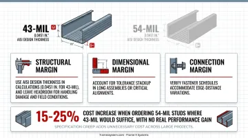
- Structural margin: Use AISI design thickness in calculations (0.0451 in. for 43-mil), and leave headroom for handling damage and field conditions
- Dimensional margin: Account for tolerance stackup in long assemblies or critical alignments
- Connection margin: Verify fastener schedules accommodate edge-distance variations
Specification creep occurs when teams specify unnecessarily heavy members. Ordering 54-mil studs when 43-mil would suffice can raise costs 15-25% with no real performance gain. Cost deltas between adjacent thickness specs add up quickly on large projects.
Key Technical Properties of CFS Specifications
Specifications encode multiple interdependent properties that together determine system performance. Changing one property without adjusting others creates failures.
Dimensional Stability and Repeatability
CFS maintains consistent dimensions across production runs, unlike wood framing, enabling prefabrication, panelization, and precise BIM coordination. This dimensional precision:
- Reduces drywall cracking by maintaining plane consistency
- Improves door and window fit through predictable rough opening sizes
- Minimizes field adjustments and finishing labor
Dimensional variability directly affects labor hours during installation and finishing trades. Tighter tolerances cut shimming, alignment corrections, and rework. Track labor-hour savings on a project-specific basis.
Material Grade and Strength Coupling
Steel grade (33 ksi vs. 50 ksi yield strength) couples with thickness to determine load capacity. You trade thinner, higher-strength steel against thicker, standard-grade material—each path changes weight, cost, and connection design.
Critical engineering consideration: Specifying higher-strength steel without adjusting thickness can produce under-capacity designs if grade is ignored in analysis.
Evaluate grade and thickness together with section geometry, buckling behavior, connections, bracing, and load cases per AISI S100. No universal capacity multiplier exists for 33 ksi versus 50 ksi substitutions.
How CFS Specifications Are Documented, Measured, and Validated
CFS specifications require clear documentation during design, accurate measurement during manufacturing and delivery, and systematic validation during construction.
Specification Documentation in Contract Documents
Specifications appear in multiple document types:
- Architectural drawings: Wall types, partition assemblies, ceiling systems, and construction details
- Structural drawings: Member sizing, load tables, connection details, and lateral bracing
- Written specifications: CSI Division 05 40 00 Cold-Formed Metal Framing (structural), Division 09 22 16 Nonstructural Metal Framing (interior partitions and supports)
Submittal packages establish compliance before material hits the site:
- Manufacturers provide mill certifications per ASTM A1003 confirming steel grade and mechanical properties
- Test reports document coating weight per ASTM A653
- Product data shows compliance with AISI standards and dimensional tolerances
- Evaluation reports (ESRs) support proprietary or non-standard products
SFIA Code Compliance Certification validates specification compliance through independent periodic plant visits and product audits. The program checks mechanical properties, coatings, dimensions, and labels for structural and non-structural studs and tracks.
Frame X Systems supports that documentation layer with BIM coordination models, engineered shop drawings, panel layout drawings, and stamped structural packages on each project. The architect-led workflow locks design intent to manufacturing data before fabrication, which reduces field RFIs and keeps specs accurate.
Measurement and Verification Methods
Field measurement needs calibrated tools and consistent technique:
- Thickness verification: Use calipers or micrometers on base metal only (exclude coating), at least 1 foot from member ends per AISI S240-20
- Dimensional checks: Tape measures for web depth (outside-to-outside for C-shapes, inside-to-inside for track) and flange width
- Straightness assessment: Straightedges or string lines for camber, bow, and twist
Two verification stages serve different purposes:
- Acceptance testing: Confirm delivered material meets specs before install. Check labels, mill certifications, spot thickness, and coating quality.
- In-place inspection: Confirm the installed assembly matches design intent. Verify member layout, connections, fasteners, bracing, and bearing conditions.
Laboratory testing per AISI S100 Section K verifies material properties when field measurements raise concerns or when using non-standard materials. Testing must use approved methods under a design professional. It is not a blanket field acceptance-test requirement.
Laboratory vs. Field Measurement Differences
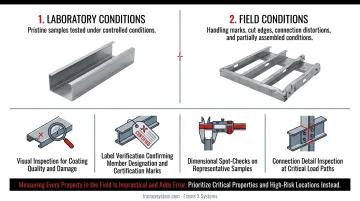
Lab tests measure pristine samples under controlled conditions. Field measurements contend with handling marks, cut edges, connection distortions, and partially assembled conditions. Practical field validation focuses on:
- Visual inspection for coating quality and damage
- Label verification confirming member designation and certification marks
- Dimensional spot-checks on representative samples
- Connection detail inspection at critical load paths
Measuring every property in the field is impractical and adds error. Prioritize critical properties and high-risk locations instead.
Implications of Operating Outside the Recommended Specification Range
Deviating from specified dimensions, materials, or tolerances (through substitution, manufacturing error, or field modification) creates predictable failure modes and compliance issues.
Structural Performance Degradation
Two failure paths show up most often:
- Under-thickness material cuts load capacity and creates unsafe conditions. Receiving 38-mil stock when 43-mil (minimum 40.85 mil) was specified falls outside tolerance and fails AISI S240.
- Connection failures follow when fastener schedules change. Altering screw size, spacing, or edge distance reduces shear or bearing capacity at critical joints. Each parameter supports assembly strength; changing one invalidates the design.
Code Compliance and Approval Risks
Deviations from specified ASTM standards, AISI design provisions, or IBC/IRC requirements void approvals and create liability for designers, contractors, and building owners. Material substitutions or non-compliant installation may void manufacturer warranties and building system warranties.
Fire Rating and Life Safety Impacts
Fire-rated assemblies are tested and listed with specific member sizes, thicknesses, and fastener schedules. UL-certified assemblies list minimum stud dimensions; larger members may be allowed only within the stated design minimums and maximums.
Unspecified modifications need an engineering judgment acceptable to the code authority. Unauthorized changes invalidate the rating and create code violations.
Common Misinterpretations of CFS Specifications in Practice
Specification errors usually come from mixed-up nomenclature or from treating structural and non-structural rules as interchangeable. These four mistakes show up most often in the field.
- Nominal dimensions as exact values — Ordering "6-inch studs" and expecting 6.000 inches ignores the ±1/32-inch tolerance. Assemblies then miss the drawn fit on site.
- Gauge numbers instead of mils — Gauge is not consistent across industries and is not the AISI designation format. Specifying "18-gauge" rather than "43 mil" or "0.0451-inch design thickness" creates order-to-delivery mismatches.
- Structural vs. non-structural mix-ups — Teams conflate AISI S240 structural framing with S220 non-structural framing. That drives costly over-spec on partitions or unsafe under-spec in load-bearing walls.
- Nominal thickness vs. design thickness — A 43-mil callout is not 0.0430-inch design thickness. AISI S240-20 Table A5-1 sets 0.0451-inch design and 0.0428-inch minimum base steel; the wrong value skews capacity checks.
Frame X Systems' architect-led design approach clears up these ambiguities before manufacturing. Constructability reviews, BIM coordination, and project-specific engineering during preconstruction catch specification errors before they hit the shop or jobsite.
That early correction saves time and cost, and it keeps unsafe substitutions out of the build.
Conclusion
Cold-formed metal framing specifications are a technical framework that ties dimensional standards, material properties, tolerance management, and compliance verification into one workable system. Strong specs reflect design intent, manufacturing limits, and field conditions, and they rely on clear documentation and validation to keep those pieces aligned.
Engineering judgment, fluency with governing standards (AISI S100/S240/S220, ASTM A1003/A653, IBC/IRC), and a clear split between structural and non-structural applications matter as much as the published numbers. Specs that build in manufacturing tolerances, real field conditions, and practical installation methods are far more likely to meet design intent without costly rework or code problems.
The gap between design specifications and installed performance closes with coordination, accurate documentation, and checks at each stage, from engineering calculations through manufacturing to field installation. Invest in that rigor during preconstruction, and you reduce RFIs, field fixes, and the failures that show up when specs are applied outside the conditions they were written for.
Frequently Asked Questions
What is the ASTM standard for cold-formed steel?
ASTM A1003/A1003M covers structural-grade CFS studs, joists, and track with minimum yield strengths of 33 or 50 ksi. ASTM A653/A653M specifies zinc-coated (galvanized) steel sheet, while ASTM A875/A875M covers zinc-5% aluminum alloy coatings for enhanced corrosion protection.
What is the CSI code for cold-formed metal framing?
CSI MasterFormat Division 05 40 00 Cold-Formed Metal Framing covers structural applications including exterior studs, joists, trusses, and roof/ceiling framing. Division 09 22 16 Nonstructural Metal Framing (under the 09 22 00 family) covers supports for plaster, gypsum board, and interior partitions. That split keeps load-bearing and nonstructural scopes from being over- or under-specified.
What are the common sizes of cold-formed metal framing?
Typical stud/joist depths include 2.5, 3.625, 6, 8, 10, and 12 inches; common flange widths are 1.25, 1.625, and 2 inches; standard thicknesses are 33, 43, 54, 68, and 97 mils. Custom sizes and profiles are available for specialized applications.
How do I verify that delivered CFS framing meets my specifications?
Check permanent labeling for member designation (e.g., 600S162-43) and certification marks, and review mill certs for ASTM A1003 compliance. Spot-check base-steel thickness with calipers at least 1 foot from member ends, inspect coating and handling damage, and compare deliveries to approved submittals.
What is the difference between design thickness and nominal thickness in CFS specifications?
Nominal thickness is the named designation (43 mil). Design thickness accounts for the -5% manufacturing tolerance: 43-mil members have 0.0451-inch design thickness and 0.0428-inch minimum delivered base steel per AISI S240-20. Use design thickness in structural calculations for code-compliant results.
Can I substitute a different thickness or grade of CFS framing in the field?
No. Substitutions need engineer approval because load capacity, connections, fire ratings, and code compliance depend on the specified properties. Unauthorized changes void warranties, invalidate fire-test listings, and can create unsafe conditions. Even thicker or higher-strength upgrades still need verification that connections, assemblies, and design assumptions remain valid.