A load-bearing wall system isn't just a vertical divider; it's the structural backbone that carries the weight of floors, roofs, and upper stories down to the foundation. According to the International Building Code (IBC), metal or wood stud walls supporting more than 100 pounds per linear foot (plf), or masonry and concrete walls supporting more than 200 plf beyond their own weight, qualify as load-bearing. Removing or weakening these elements without replacement support can trigger progressive failure and partial or complete structural collapse.
Key Takeaways
- Load-bearing walls carry roof and floor loads to the foundation; partition walls only divide space
- Common materials include masonry, poured concrete, wood framing, and cold-formed steel—each with different strength and cost profiles
- Headers and lintels span openings and redirect loads to the wall sections on each side
- Get a professional engineering assessment before removing or altering any suspected load-bearing wall
What Is a Load-Bearing Wall System?
Load-bearing walls are structural elements that support vertical loads from upper floors, roofs, and occupants. They transfer that weight down through the building to the foundation.
Unlike partition walls that only divide interior space, load-bearing walls act as the building’s skeleton. They maintain structural integrity and help prevent settlement or collapse.
Structural Function and Load Transfer
Per the IBC definition of bearing-wall structures, floors and roofs bear primarily on continuous walls. Those walls spread concentrated loads across the foundation and into the soil below.
That load path limits differential settlement that can crack walls, tilt floors, and damage the building envelope. Think of the system as a continuous stack of vertical supports that must stay intact and properly connected from roof to foundation.
A complete load path requires positive connections at every interface:
- Roof sheathing fastened to roof framing
- Roof framing anchored to wall top plates
- Walls connected continuously from top to bottom
- Wall bottom plates secured to foundations
- Foundations bearing on engineered, compacted soil
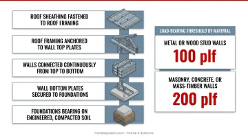
Key distinction: The threshold for load-bearing classification varies by material. Metal or wood stud walls become load-bearing when they support more than 100 plf of additional vertical load, while masonry, concrete, or mass-timber walls cross that threshold at 200 plf.
Historical Evolution
Load-bearing construction goes back to ancient masonry buildings, where stone or brick walls carried the full structural load. Historic builders often used low-strength lime mortar that could handle settlement and thermal movement, so walls flexed instead of cracking.
Medieval builders pushed the idea further with Gothic flying buttresses. Those elements moved horizontal thrust from vaulted ceilings down to the ground and kept arches from developing unwanted tension.
Modern work moved from masonry-only walls to engineered light-frame systems with wood studs, then to cold-formed steel framing. CFS brings dimensional stability, fire resistance, and resistance to rot and termites.
Today’s load-bearing assemblies pair those materials with engineered connections and coordinated models so performance under code-specified loads is predictable before the panels reach the site.
Non-Load-Bearing vs. Load-Bearing Walls
The difference lies entirely in structural function, not appearance:
- Load-bearing walls support weight from above and transfer it to the foundation
- Non-load-bearing (partition) walls only divide space; they carry no structural load beyond their own weight
Visual clues like wall thickness, location, or construction material can suggest load-bearing status, but only engineered plans or professional structural assessment confirm it definitively.
Key Components of Load-Bearing Wall Systems
Foundation and Footings
Foundations distribute concentrated wall loads across the soil, preventing uneven settlement that can crack walls or tilt floors. The 2024 IRC requires footing width to match tributary load and allowable soil pressure; prescriptive concrete footings measure at least 12 inches wide and 6 inches deep. Where fill supports foundations, accepted engineering design, installation, and testing are required.
Wall Framing Elements
Wood framing: The American Wood Council (AWC) specifies that one- and two-story exterior walls use at least nominal 2x4 studs. Standard spacing is 16 inches on center; 24-inch spacing is acceptable for one-story buildings only when adequate sheathing or siding provides bridging. Three-story buildings require heavier bottom-story studs (at least nominal 3x4 or 2x6) at no more than 16 inches on center. Sill plates connect wood-framed walls to foundations.
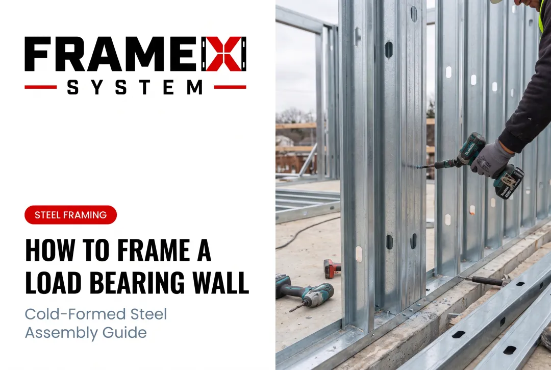
Cold-formed steel (CFS): AISI S240-20 requires uniform bearing surfaces, limits the foundation-to-bottom-track gap to 1/4 inch, and mandates stud-to-track connections that restrain rotation and transverse displacement. Plates (top and bottom tracks) anchor the wall assembly, while studs transfer vertical loads. Prefabricated CFS panels package those same elements before they reach the site. Frame X Systems delivers architect-led, BIM-coordinated load-bearing wall panels built from precision roll-formed studs, horizontal top and bottom tracks, and diagonal reinforcements. Each project ships with engineered shop drawings, BIM models, stamped structural packages, and labeled components sequenced for install, which cuts field labor, RFIs, and change orders.
Headers and Lintels
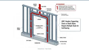
When door or window openings interrupt a load-bearing wall, loads above the opening must be redirected. Headers span the opening and transfer accumulated weight to supporting wall sections—typically doubled or tripled studs—on either side. The header, bearing studs, connections, and foundation path must all be sized together; undersizing any component can cause localized overload and failure. AWC notes that headers supporting floors or roofs above require multiple studs for end bearing.
Bracing and Shear Elements
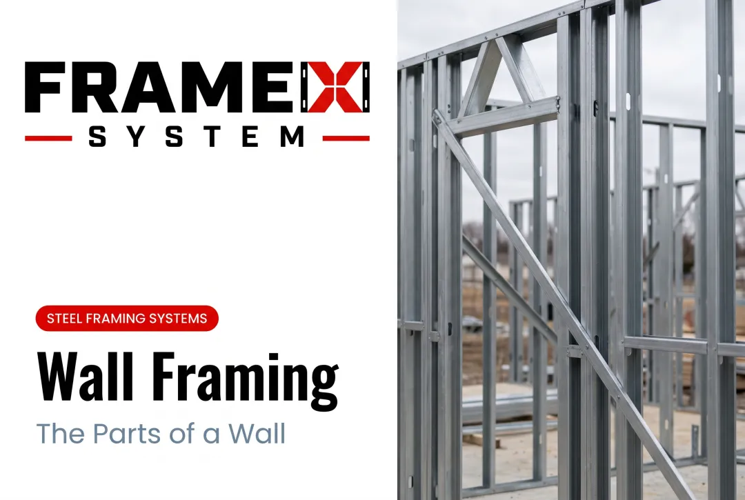
IRC braced-wall provisions vary with wind speed; the IBC requires continuity of the load path where wall framing is discontinuous from sill to roof. Bracing systems include:
- Diagonal let-in bracing embedded in wood stud walls
- Structural plywood or OSB sheathing fastened to studs and plates
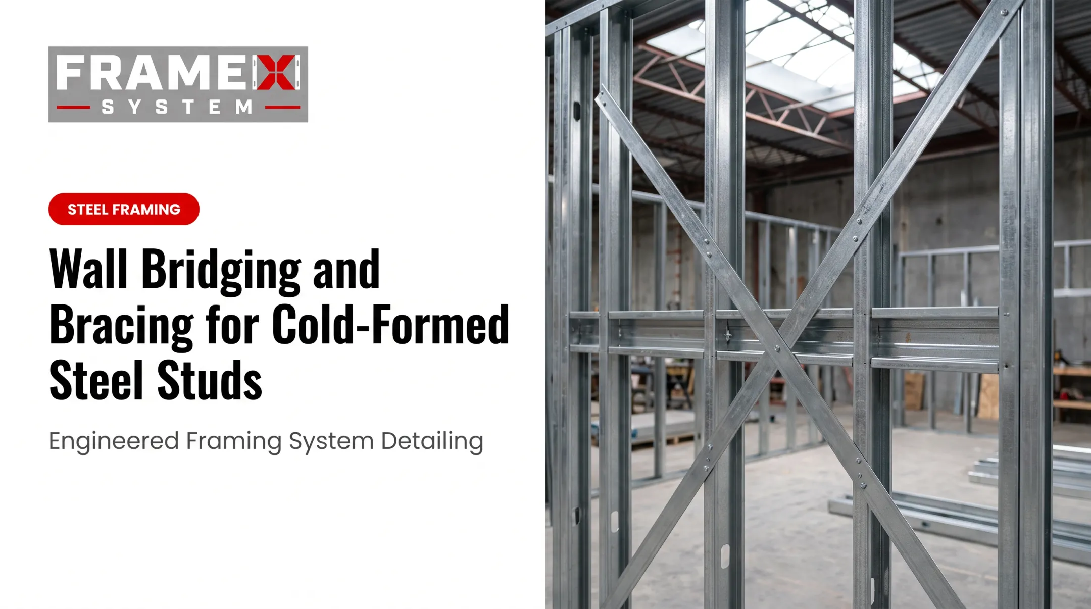
- Steel X-bracing or flat straps in steel framing
- Hold-downs anchoring shear walls to foundations
These elements resist lateral forces—wind, seismic, and soil pressure—that push walls sideways, preventing racking and maintaining plumb alignment.
Wall Tie-Ins and Connections
A complete load path depends on mechanical connections at intersecting walls, floor joists, and roof trusses. Required elements include:
- Roof-to-wall anchors (hurricane clips, straps, or direct nailing)
- Wall-above-to-wall-below continuity (stacked studs, continuous sheathing, or metal connectors)
- Wall-to-foundation hold-downs and anchor bolts
- Floor joist hangers or bearing connections to wall top plates
Each connection must be sized to transfer the applied load; a single weak link can trigger progressive collapse.
Reinforcement Systems
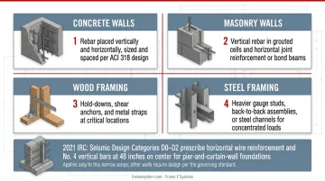
Reinforcement increases tensile strength and resists lateral movement:
- Concrete walls: Rebar placed vertically and horizontally, sized and spaced per ACI 318 design
- Masonry walls: Vertical rebar in grouted cells and horizontal joint reinforcement or bond beams
- Wood framing: Hold-downs, shear anchors, and metal straps at critical locations
- Steel framing: Heavier gauge studs, back-to-back assemblies, or steel channels for concentrated loads
The 2021 IRC specifies one reinforcement example: pier-and-curtain-wall foundations in seismic design categories D0-D2 prescribe horizontal wire reinforcement and No. 4 vertical bars at 48 inches on center. This detail applies only to that narrow scope; other walls require design per the governing standard.
Types of Loads in Load-Bearing Structures
Load-bearing walls must carry every force a building will see over its life. Codes group those forces into distinct load types, each with its own minimums and combination rules.
Dead Loads (D)
Dead loads are permanent, static weights from the structure itself: framing, sheathing, roofing, cladding, and fixed equipment. Engineers calculate these from actual construction-material weights plus fixed service equipment. Unknown values require building-official approval.
A typical residential floor assembly might impose 10–15 pounds per square foot (psf) dead load. A concrete floor with heavy finishes can reach 50–80 psf.
Live Loads (L)
Live loads are temporary, variable weights from occupancy—people, furniture, and movable equipment. The 2024 IBC sets minimum live loads by occupancy type:
- Private rooms and corridors in one- and two-family dwellings: 40 psf
- Offices: 50 psf plus a 2,000-pound concentrated load
- Fixed-seat assembly: 60 psf
- Movable-seat or other assembly: 100 psf
- Stages: 150 psf
Actual design values may exceed these minimums when specific uses or conditions warrant higher loads.
Lateral and Environmental Loads (W, E)
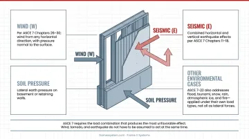
Lateral loads push horizontally on walls and must be resisted at the same time as gravity loads:
- Wind (W): Per ASCE 7 Chapters 26–30; wind from any horizontal direction, with pressure normal to the surface
- Seismic (E): Combined horizontal and vertical earthquake effects per ASCE 7 Chapters 11–18
- Soil pressure: Lateral earth pressure on basement or retaining walls
- Other environmental cases: ASCE 7-22 also addresses flood, tsunami, snow, rain, atmospheric ice, and fire—applied under their own load types, not all as lateral forces
ASCE 7 requires the load combination that produces the most unfavorable effect. Wind, tornado, and earthquake do not have to be assumed to act at the same time.
Common Materials for Load-Bearing Walls
Masonry (Brick and Concrete Block)
Concrete masonry units (CMUs) come in nominal thicknesses of 4, 6, 8, 10, 12, 14, and 16 inches, with a standard nominal face of 8 x 16 inches. ASTM C90 requires minimum unit net-area compressive strength of 2,000 psi.
Traditional load-bearing construction uses 8-12 inch walls, but actual thickness depends on TMS 402 design, geometry, tributary loads, reinforcement, and the adopted code—not just block dimensions.
Applications: Low-rise buildings (typically 2-3 stories) with repetitive cellular layouts. Taller masonry construction requires engineered reinforcement and may transition to concrete or frame systems.
Limitations: Unit strength is not assembled-wall strength; mortar quality, reinforcement placement, and grouting affect capacity. Masonry is heavy, labor-intensive, and less forgiving of field modifications than frame systems.
Poured Concrete
Reinforced concrete walls use rebar for tensile strength, with high capacity for mid-rise buildings and flexibility for complex geometries. They tie into concrete floors and foundations as monolithic structures with strong fire resistance and durability.
Design variables: Concrete strength (f'c), wall thickness, reinforcement ratio, slenderness, opening sizes, and lateral role must all be specified per the adopted IBC and ACI 318 design standards. No universal thickness, strength, or height limit applies across all projects.
Applications: Mid-rise residential, commercial, and institutional buildings; below-grade walls resisting soil pressure; cores and shear walls in taller structures.
Wood Framing
Platform framing with 2x4 or 2x6 studs dominates residential construction due to ease of construction, cost-effectiveness, and availability. AWC prescriptive examples show nominal 2x4 exterior studs for one- and two-story buildings, with heavier bottom-story studs required for three stories. Typical applications include 1-3 story buildings with wood or engineered lumber floor systems and wood roof trusses.
Advantages: Widely available, familiar to trades, accommodates wiring and plumbing easily, and supports quick construction schedules.
Limitations: Susceptible to warping, shrinking, twisting, moisture damage, rot, and termites. Fire performance requires additional rated assemblies. Capacity changes with species, grade, height, spacing, tributary load, and bracing.
Cold-Formed Steel Framing
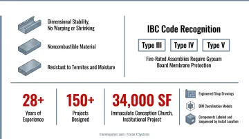
Engineered steel stud systems use precision roll-formed galvanized steel members that offer dimensional stability, noncombustibility, and resistance to termites and moisture. CFS does not warp, shrink, or twist like wood, delivering predictable field fit and reducing callbacks.
Code recognition: CFS is recognized as noncombustible, supporting Type III, IV, and V construction under the IBC. Fire-rated assemblies depend on membrane protection (gypsum board) and tested configurations.
Applications: Multifamily housing, commercial buildings, mixed-use developments, and institutional facilities where fire resistance, dimensional consistency, and long-term durability are priorities.
Frame X Systems integration: FrameX supplies architect-led, BIM-coordinated cold-formed steel framing that arrives installation-ready. Load-bearing wall panels use precision-manufactured steel studs, horizontal tracks, and diagonal reinforcement.
Project packages typically include:
- Engineered shop drawings and stamped structural packages
- BIM coordination models
- Components labeled and sequenced by install location
That coordination reduces RFIs, field labor, and change orders while keeping steel’s fire resistance and dimensional accuracy. FrameX has 28+ years of experience and 150+ designed projects, including institutional work such as the 34,000-square-foot Immaculate Conception Church.
Load-Bearing vs. Frame Structure Systems
Choosing between load-bearing walls and a column-and-beam frame shapes layout flexibility, renovation options, and cost. Use the comparison below, then weigh the decision factors against your building type and project horizon.
| System | How It Works | Best Applications | Trade-offs |
|---|---|---|---|
| Load-bearing wall | Floors and roofs bear primarily on continuous walls; walls distribute gravity loads to foundations | Low-rise buildings (1-4 stories), cellular layouts (apartments, hotels, dormitories), repetitive floor plans | Cost-effective and structurally simple; interior walls limit future layout changes; removing a wall requires replacement support |
| Column/beam frame | Concentrated columns and beams carry gravity loads; infill walls need not be structural | Mid- to high-rise buildings, open floor plans (offices, retail, assembly), projects anticipating future reconfiguration | Greater planning flexibility; higher material and connection costs; frame alterations remain engineered work |
Decision Factors
Height: Neither system has a fixed story limit on its own. Limits depend on construction type, occupancy, fire protection, lateral system, wall slenderness, and the adopted code.
Layout flexibility: U.S. Air Force WBDG guidance recommends minimizing interior bearing walls and columns and coordinating required walls with building cores to keep planning open. Frame systems handle later repartitioning more easily; load-bearing systems fit fixed, repetitive room layouts well.
Renovation horizon: Removing a load-bearing wall interrupts a distributed load path and normally requires replacement beams, posts, and foundations. Nonbearing infill in frame structures can change more readily, though every structural alteration still needs engineering review.
Cost: Material, labor, fire ratings, foundations, and local markets vary too widely for a single national cost-per-square-foot figure. Compare project bids with identical loads, spans, and scope.
How to Identify Load-Bearing Walls
Visual Clues (Screening Only)
These conditions often suggest a wall is load-bearing—use them only as a first screen:
- Walls perpendicular to floor joists
- Walls along the building’s center line
- Exterior walls
- Walls directly above beams or foundations
- Thicker-than-typical wall construction
WoodWorks explicitly warns that beams or columns in the wall plane do not by themselves establish bearing status. Visual thickness or a central location is not proof.
Check Original Structural Plans
Blueprints locate bearing walls, headers, beams, and members that support loads from above on floor and framing plans. Foundation plans show footings, reinforcing, and concrete strength. Bearing walls often appear with special notation or heavier line weights.
Field Trace (Attic, Basement, Crawlspace)
Inspect from above and below to trace load paths. Focus on:
- Where joists or trusses end or overlap
- Where beams or posts occur
- Whether support continues to the foundation
Walls with beams, columns, or footings directly below or above are likely load-bearing.
Professional Assessment Required
Visual clues and plan review only narrow the candidates. They do not replace engineering verification. Portland is one jurisdiction requiring structural plan review for construction and alterations; calculations and registered-professional stamps apply when required by code. Removing or altering a suspected load-bearing wall without proper engineering can cause catastrophic failure.
Frequently Asked Questions
What is the difference between a load-bearing wall and a regular wall?
Load-bearing walls support structural weight from floors, roofs, or upper stories and transfer it to the foundation. Regular (partition) walls only divide interior space and carry no load beyond their own weight. The distinction depends on tributary load and code thresholds, not appearance.
How thick does a load-bearing wall need to be?
Thickness varies by material, height, and design. Wood-framed walls typically measure 4–6 inches (nominal 2x4 or 2x6 studs plus sheathing); masonry often runs 8–12 inches nominal. Final size comes from engineered calculations for tributary load, wall height, and code—not a universal dimension.
How much does a load-bearing wall cost?
Cost depends on material, height, span, openings, reinforcement, code requirements, engineering, and permits. Use regional, project-specific bids rather than national averages. Older references cite wood framing around $8–15/sq ft and masonry around $15–30/sq ft, but local markets vary widely.
Can you remove a load-bearing wall during renovation?
Yes, if you replace it with proper structural support. Establish a temporary and permanent load path with an engineered header or beam, end posts or columns, connections, and support below (continuous load path guidance). Submit calculations and plans to the authority having jurisdiction and obtain permits before work starts.
What happens if a load-bearing wall fails?
An incomplete or understrength load path can cause sagging floors, cracked finishes, misaligned doors and windows, and in severe cases progressive collapse. Early signs include new cracks, binding doors, or sloping floors.
Do all exterior walls carry loads?
Most exterior walls in traditional construction are load-bearing, but not all. In frame structures with curtain wall systems, exterior walls may be nonbearing cladding that transfers only wind load, not floor or roof loads. Verify status through structural plans or engineering assessment.
Final Word
Load-bearing wall systems transfer vertical and lateral loads safely to the foundation. Before new construction or renovation, confirm which walls carry load and how that path works.
Always consult a licensed structural engineer before altering any suspected load-bearing wall. Complete engineered plans, permits, and inspections for every structural modification.