Introduction
Every general contractor and architect has encountered the same field problem: framing conflicts discovered during installation that should have been caught in the design phase. When cold-formed steel framing details are unclear, incomplete, or uncoordinated, the jobsite pays the price. RFIs multiply, schedule delays cascade, and crews spend billable hours cutting, drilling, and modifying members that should have arrived installation-ready.
According to a 2022 study of 17 high-rise construction projects, 65% of the 2,690 RFIs analyzed were clarification requests, including 1,098 cases of insufficient information and 506 conflict cases. Researchers estimated that 3D coordination could have prevented 434 of those issues—evidence that many framing problems originate long before the first panel leaves the truck.
This guide covers light-gauge steel framing components, connection details by building system, structural design considerations, BIM coordination, fabrication efficiency, and common mistakes that drive costly field corrections.
Whether you're specifying wall studs, engineering truss-to-wall connections, or coordinating MEP penetrations, these details determine whether your project moves smoothly or stops for clarifications.
Key Takeaways
- Cold-formed steel under 1/8" is governed by AISI S100, S240, S220, and S202 for different system types
- Specify mil thickness (33, 43, 54, 68, 97), not gauge alone—equivalent and structural products can share labels
- Connection design is assembly-specific; generic screw schedules do not satisfy AISI S240 requirements
- BIM coordination resolves MEP clashes before fabrication and reduces RFIs
- Deflection criteria depend on member function, finish type, and load case, not a single universal limit
Understanding Light Gauge Steel Framing Components
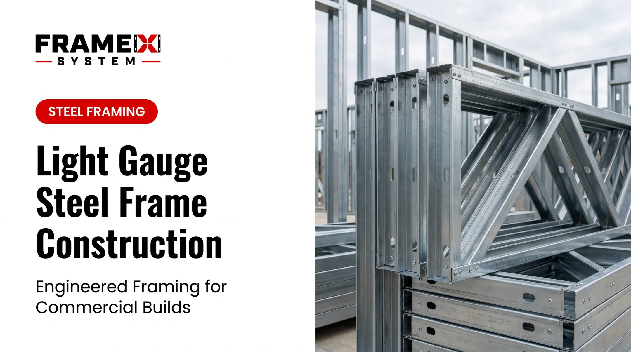
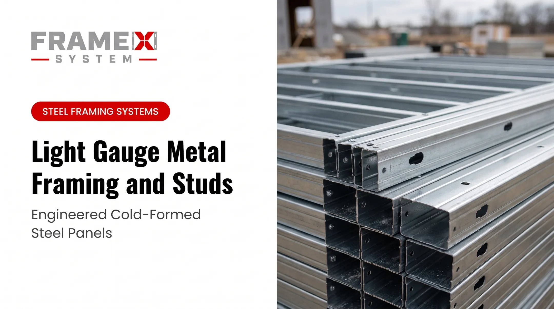
Cold-formed steel framing starts as structural-quality sheet steel fed through roll-forming machines. Dies shape the material at room temperature into C-shaped studs, tracks, joists, and other profiles.
Unlike hot-rolled structural steel, light-gauge framing means cold-formed members under 1/8" thick—used for wall studs, floor joists, and roof trusses.
Thickness and Gauge Designation
The gauge designation system runs inversely to thickness: lower gauge numbers mean thicker material. Structural and equivalent non-structural products can share the same gauge label despite different design thicknesses.
For example, ClarkDietrich structural C-Series products offer:
- 20-gauge = 33 mil (0.0329")
- 18-gauge = 43 mil (0.0428")
- 16-gauge = 54 mil (0.0538")
- 14-gauge = 68 mil (0.0677")
- 12-gauge = 97 mil (0.0966")
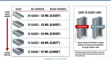
Always specify mil thickness or design thickness on drawings and submittals, not gauge numbers alone. A 20-gauge structural stud and a 20-gauge non-structural stud may have different load capacities, flange widths, and code classifications.
Key Framing Member Types
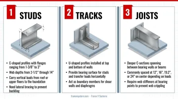
Studs (vertical members):
- C-shaped profiles with flanges ranging from 1-3/8" to 3"
- Web depths from 2-1/2" through 14"
- Carry vertical loads from roof or upper floors to the foundation
- Need lateral bracing to prevent buckling
Tracks (horizontal channels):
- U-shaped profiles installed at top and bottom of walls
- Provide bearing surface for studs and transfer loads horizontally
- Act as boundary members for shear walls and diaphragms
Joists (floor/ceiling spanning members):
- Deeper C-sections spanning between bearing walls or beams
- Commonly spaced at 12", 16", 19.2", or 24" on center depending on loads
- Require web stiffeners at bearing points to prevent web crippling
Structural vs. Non-Structural Classification
The distinction between structural and non-structural members is governed by AISI standards, not merely thickness or flange width:
- AISI S240-20 governs structural framing—floors, roofs, structural walls, shear walls, strap-braced walls, diaphragms, and trusses per the 2024 IBC
- AISI S220-20 governs non-structural framing—interior partitions not designed to resist building loads
Structural studs typically feature:
- Wider flanges (1-5/8" to 3") for connection capacity and stiffness
- Thicker material (43 mil and up for most load-bearing applications)
- Higher-strength steel (50 ksi for 54, 68, and 97 mil products)
- CP60 or G60 galvanizing for corrosion resistance
Non-structural studs may include:
- Narrower flanges (1-1/4" common for drywall framing)
- Thinner gauges (15, 18, 30, 33 mil in some product lines)
- Lower-strength steel (33 ksi acceptable for non-load-bearing applications)
- G40 galvanizing sufficient for interior conditions
Material Specifications and Labeling
Steel strength is designated by yield stress:
- 33 ksi steel: Common in lighter structural and non-structural applications
- 50 ksi steel: Standard for heavier structural members (54 mil and thicker)
Galvanizing standards indicate coating weight and protection level:
- G40: Minimum coating, interior use only
- G60: Standard coating for most structural applications
- G90: Heavy coating for severe exposures
- CP60/CP90: Coating with additional polymer layer for enhanced corrosion resistance
Manufacturer labels typically include member designation (e.g., 600S162-54), where:
- 600 = web depth in hundredths of an inch (6.00")
- S = stud
- 162 = flange width in hundredths of an inch (1-5/8")
- 54 = design thickness in mils
Standard Spacing Conventions
While 16" and 24" on-center spacing are common layout defaults, actual spacing must be validated by load tables and span calculations. Factors affecting spacing include:
- Dead and live loads
- Member size and thickness
- Unbraced length and lateral support conditions
- Deflection limits for finish materials
- Sheathing or gypsum board attachment requirements
Do not treat standard spacing as a universal capacity assumption. Always reference current manufacturer tables or perform engineering calculations using AISI S100.
Essential Connection Details by Building System
AISI S240-20 does not prescribe universal screw counts for all stud-to-track or joist-to-track connections. Instead, it requires assembly-specific design under AISI S100, which evaluates shear, tension, bearing, and edge-distance limit states for each connection.
Generic schedules copied from one project to another often fail to account for member thickness, steel grade, load magnitude, and fastener type.
Wall Framing Details
Stud-to-Track Connections
AISI S240 Section C3.4.3 requires that flange connections restrain stud rotation and displacement. For axial load-bearing studs of 54 mil or less, the standard mandates:
- Square-cut stud ends
- Tight bearing contact with track (maximum 1/8" gap)
- Fasteners through both flanges into track
Screw type, quantity, spacing, and edge distance remain design variables evaluated under AISI S100. A typical connection might use:
- Two #8 self-drilling screws per flange (four total per stud)
- Minimum 3/8" edge distance from fastener centerline to sheet edge
- Fasteners placed within 1" of stud end
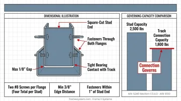
Key consideration: Connection capacity must exceed the stud's design load. If the stud can resist 2,500 lbs in compression, but the track connection fails at 1,800 lbs, the connection governs.
Header Assemblies Over Openings
AISI S240 Section C3.4.4 recognizes back-to-back and box headers. For box headers, the standard permits:
- #8 screws at 24" on center connecting header flanges
- 1" fillet welds at 24" on center (accepted alternative)
Do not assign generic span ranges. Header capacity depends on:
- Member depth, thickness, and steel grade
- Opening width and tributary load
- Jamb stud capacity and bearing length
- Deflection limits (varies by finish and occupancy)
Select headers from current manufacturer tables (such as SFIA Technical Guide 2025.1) or perform engineering calculations. A 600S162-54 back-to-back header spanning 6 feet under one load condition may be undersized for the same span under different tributary loads.
Jamb Stud and King Stud Arrangements
Jamb studs directly support header ends and must be sized for bearing:
- Verify web crippling capacity at header bearing location
- Add web stiffeners if required by AISI S100 calculations
- Fasten header flanges to jamb stud flanges with screws at specified spacing
King studs—full-height studs beside the jambs—add support and sheathing anchor points. Jamb and king studs must both carry header reactions through their bearing connections into the bottom track and foundation.
Floor and Ceiling Framing Details
Joist-to-Track and Rim Track Assemblies
AISI S240 Section C3.3.3 requires:
- Full bearing over the wall, OR
- Minimum 1-1/2" end bearing unless specifically engineered otherwise
- Joist and rim-track webs must not contact directly
Rim track acts as a bearing seat and lateral restraint for joist ends. Typical connection details include:
- Two screws through joist web into rim track
- Clip angles when shear or uplift demands exceed screw capacity
- Continuous bridging or blocking at mid-span when joist span exceeds 8 feet
Different floor elevations and transitions require:
- Stepped rim tracks with proper bearing at each level
- Coordinated header depths to maintain floor-plane continuity
- Additional framing to support transition zones
Web Stiffeners and Blocking
Concentrated loads, such as point loads from beams or heavy equipment, can cause local web buckling (web crippling) at joist bearings. AISI S240 Section B2.5 addresses web-crippling reinforcement.
For clip-angle stiffeners, the standard specifies:
- Three screws connecting stiffener legs to joist web and rim-track web
- #8 or #10 screws selected based on angle thickness
- Stiffener placement directly at bearing point
Follow the complete geometry and strength checks in AISI S240. Do not assume that adding any stiffener automatically satisfies bearing requirements: stiffener size, fastening, and placement must be calculated.
Roof Framing Details
Truss-to-Wall Connections
AISI S240 Section C3.5.3 requires:
- Full bearing or minimum 1-1/2" end bearing unless specifically engineered
- Vertical, in-plane installation at specified spacing
- Proper bracing per truss design
Bearing clips transfer vertical reactions and resist uplift from wind loads. Connection details vary by truss configuration and load:
- Simpson or equivalent bearing clips with published capacities
- Fasteners through clip into truss chord and top track
- Lateral bracing integration at truss-panel points
Bottom-chord bracing: AISI S240 notes a suggested 10-foot maximum spacing for permanent bottom-chord restraint, based on limited testing and field experience, not a universal design value. Verify bracing requirements with the truss manufacturer's engineered design.
Purlin Splicing and Roof Overhangs
Continuous roof framing members spanning multiple supports require:
- Splice connections designed for moment, shear, and axial forces
- Adequate bearing length at intermediate supports
- Proper attachment to resist uplift
For roof overhangs, cantilever capacity depends on:
- Member size and unbraced length
- Uplift and gravity load combinations
- Lateral bracing of compression flange
Do not extend standard purlin or joist products beyond their tested configurations without engineering review.
Structural Design Considerations
Light gauge steel only performs as designed when load path, spans, bracing, deflection, and connections are checked together. Size members in isolation and the system still fails at the weak link—usually a missing brace, soft span assumption, or undersized fastener group.
Load Path and System Behavior
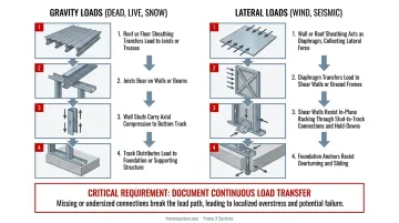
A complete load path traces how forces travel from their point of application to the foundation. For cold-formed steel framing:
Gravity loads (dead, live, snow):
- Roof or floor sheathing transfers load to joists or trusses
- Joists bear on walls or beams
- Wall studs carry axial compression to bottom track
- Track distributes load to foundation or supporting structure
Lateral loads (wind, seismic):
- Wall or roof sheathing acts as diaphragm, collecting lateral force
- Diaphragm transfers load to shear walls or braced frames
- Shear walls resist in-plane racking through stud-to-track connections and hold-downs
- Foundation anchors resist overturning and sliding
Critical requirement: Document continuous load transfer. Missing or undersized connections break the load path, leading to localized overstress and potential failure.
Allowable Spans and Heights
No universal "allowable span" exists for cold-formed steel members without specifying:
- Member designation (web depth, flange width, thickness)
- Spacing (12", 16", 24" O.C., etc.)
- Steel grade (33 ksi or 50 ksi)
- Bracing and sheathing assumptions
- Load magnitude (dead + live)
- Bearing conditions
- Deflection criteria
Use SFIA Technical Guide 2025.1 or manufacturer load tables with matching inputs. A 10-foot span that works for one load and spacing combination may be overstressed under different conditions.
Limiting heights for studs assume continuous lateral support on both flanges over the full height. Incomplete wallboard installation or unsheathed conditions may require separate bracing until finishes are in place.
Lateral Bracing Requirements
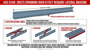
Compression members buckle when unbraced length exceeds critical limits. AISI S240 prescriptive provisions for floor/ceiling joists spanning over 8 feet require:
- Tension-flange lateral bracing
- Intermediate braces at maximum 8-foot spacing
- Continuous straps on tension flanges at max 12 feet O.C. (when used instead of discrete braces)
Bracing types:
- X-bracing: Diagonal members crossing between parallel studs or joists
- K-bracing: Diagonal members connecting from mid-height of one member to bearing point of adjacent member
- Continuous bracing channels (CRC): Hat channels or straps screwed continuously to tension flanges
Key principle: Bracing must be adequately fastened and must itself resist buckling. A thin strap without sufficient stiffness does not provide effective restraint.
Deflection Criteria and Serviceability
Strength calculations confirm a member won't fail, but serviceability ensures it won't deflect excessively under load. 2024 IBC Section 1604.3 and Table 1604.3 establish deflection limits based on:
- Member function (floor joist, roof rafter, partition stud)
- Finish type (plaster, gypsum board, flexible finishes)
- Load case (live load only, total load, wind, etc.)
Do not assume L/360 or L/240 as universal limits. Select the appropriate row from Table 1604.3:
- Roof members supporting plaster ceiling: L/360 for live load
- Floor members: L/360 for live load (common), but verify with project specifications
- Exterior walls with brittle finishes: May require L/240 or L/360 for total load
Also check cladding deflection limits, door and window operation clearances, and occupant comfort (floor vibration).
Connection Design Principles
Every connection must resist applied forces without exceeding limit states:
- Tension: Fastener pullout or net-section failure
- Shear: Fastener shear or bearing of fastener against sheet
- Bearing: Local yielding or tearing of connected sheet
Simpson Strong-Tie Cold-Formed Steel Connector Catalog C-CF-2026 provides 244 pages of connector specifications, load tables, and installation requirements. Do not extract a single capacity value without verifying:
- Screw size and type (#8, #10, #12, etc.)
- Connected-sheet design thickness (both members)
- Steel strength (33 ksi or 50 ksi)
- Edge distance and spacing
- Load direction (shear, tension, combined)
- ASD or LRFD basis
- Footnotes and installation conditions
Typical fastener capacities are assembly-specific and sensitive to installation quality. Three exposed threads and no permanent separation of connected parts are required by AISI S240 Section C4.1.2.
BIM Coordination and Design Integration
RFI Reduction Through Early Coordination
A 2022 analysis of 2,690 RFIs from 17 Chilean high-rise projects found that 65% were clarification requests, including 1,098 insufficient-information cases and 506 conflict cases. Researchers estimated that 3D coordination could have prevented 434 selected RFIs.
While this study did not isolate cold-formed steel framing specifically, it still shows the value of early interdisciplinary coordination.
Separate research reviewed by ASCE in 2011 reported up to 40% elimination of unbudgeted changes through BIM adoption across various project types. Treat these findings as broad evidence supporting coordination workflows, not guaranteed CFS-specific results.
BIM Workflow for CFS Framing
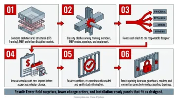
Federated model coordination:
- Combine architectural, structural (CFS framing), MEP, and other discipline models
- Classify clashes among framing members, MEP routes, openings, and equipment
- Route each clash to the responsible designer (structural, mechanical, electrical, or plumbing)
- Assess schedule and cost impact before accepting a design change
- Resolve conflicts, re-coordinate the model, and verify clash elimination
- Freeze opening locations, punchouts, headers, and connection zones before releasing shop drawings
Result: Fewer field surprises, fewer change orders, and installation-ready panels that fit as designed.
Frame X Systems builds this coordination into every project workflow—delivering federated models, flagging MEP conflicts, verifying opening dimensions, and locking penetration locations before fabrication starts.
Automated Shop Drawing Generation
Properly coordinated BIM models enable:
- Accurate stud, track, and fastener quantities from automated takeoffs
- Panel layout drawings with labeled components and installation sequence
- Sequenced delivery schedules tied to the construction workflow
These outputs cut manual drafting time and improve accuracy, but only when the model is complete. Incomplete or uncoordinated models still force field corrections and undercut the point of prefabrication.
Design for Fabrication and Installation Efficiency
Panelization Strategies
Panel size limits balance structural continuity, transportation constraints, and handling capacity:
- Transportation: Maximum truck width (typically 8'6" without permit), height clearance, and route restrictions
- Handling: Crane capacity, rigging points, panel stiffness during lifting
- Connection continuity: Splice details at panel joints must transfer shear, moment, and axial loads
AISI S202-20 requires panel fabrication documents to state:
- Member profile, depth, thickness, length, coating, and yield strength
- Panel IDs and quantities
- Fastener counts and locations
- Connection hardware and reinforcement
- Panel placement diagrams identifying every panel and adjacent structural elements
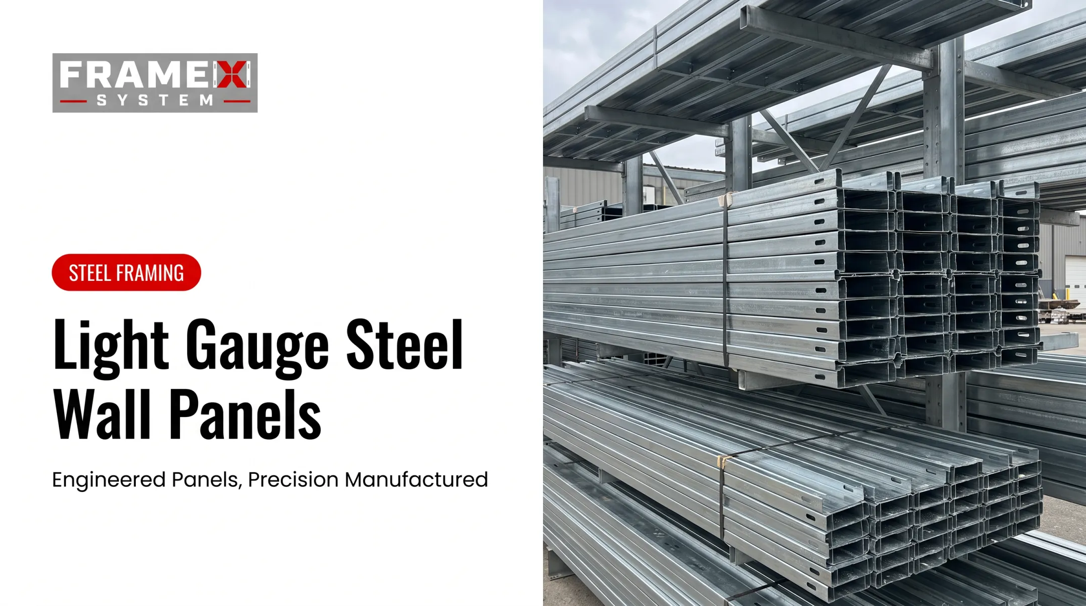
Those documents drive shop production and field sequencing. Frame X Systems manufactures wall panels to project specifications, labeled and sequenced by installation location. Panels arrive bundled for unloading, with installation documentation and stamped structural packages included.
Standardization and Repetition
Panelization pays off faster when details repeat. Keep complexity down with consistent assemblies:
- Use consistent member sizes across similar applications (for example, all interior non-load-bearing walls with 600S162-33 studs at 24" O.C.)
- Standardize connection details (same screw type, spacing, and edge distance for all stud-to-track connections of a given type)
- Coordinate typical opening dimensions to allow repeated jamb assemblies
Trade-off: Standardization improves fabrication speed and installation predictability, but it cannot override member-specific span, deflection, or connection calculations. Use repeatable details only after verifying their design envelope.
Efficient Installation Design
With members and connections locked in, design the install sequence for access, simple fastening, and fewer crane moves.
Provide adequate tool access:
- Maintain minimum 2" clearance for screw gun nose
- Avoid back-to-back or overlapping members that block fastener placement
- Coordinate blocking and bridging to allow screw installation from accessible side
Avoid overly complex connections:
- Limit connection steps (fewer parts, fewer fastener types)
- Use published connector products (Simpson clips, angles) instead of field-fabricated assemblies
- Sequence panel placement to minimize crane moves and repositioning
Pre-coordinate penetrations:
- Keep web holes within approved sizes and locations per AISI S240
- Obtain registered design professional approval when structural web holes exceed those limits
- Prohibit field cutting, drilling, notching, or splicing without written approval per AISI S202-20
Coordinate penetrations with MEP trades during BIM coordination, then manufacture panels with pre-punched or pre-cut openings.
Common Design Mistakes to Avoid
Most light gauge steel framing failures in the field trace back to a few repeatable design gaps—not exotic edge cases. Catching these five mistakes in design and shop drawings prevents rework, schedule slips, and capacity shortfalls.
Undersized or Improperly Supported Headers
Error: Selecting headers based on span alone without verifying tributary load, deflection, and jamb capacity.
Consequences: Overstressed jambs, excessive header deflection, cracked finishes, and doors or windows that bind.
Control:
- Calculate tributary area and apply dead + live loads
- Select header depth and thickness from manufacturer tables matching load and span
- Verify jamb stud capacity at bearing location
- Check web crippling and add stiffeners if required
- Confirm deflection meets finish and operational requirements (doors, windows)
Inadequate Lateral Bracing
Error: Assuming gypsum board or sheathing always provides full lateral restraint without verifying attachment and stiffness.
Consequences: Member buckling under compression, reduced capacity, and potential collapse.
Control:
- Reference limiting-height tables with stated bracing assumptions
- Provide designed X-bracing, K-bracing, or continuous straps when sheathing is incomplete or removed
- Verify bracing attachment (screw spacing, edge distance) meets design requirements
- Install temporary bracing during construction until permanent restraint is in place
Tolerance and Clearance Issues at Openings
Error: Failing to account for proper jamb clearances, header heights, and installation tolerances, resulting in field modifications and schedule delays.
Consequences: Field-cut members, misfit frames, change orders, and delayed enclosure.
Control:
- Specify jamb clearances (typically 1/2" to 3/4" for door frames)
- Verify rough opening dimensions with door/window manufacturer requirements
- Coordinate header height with finish floor and ceiling elevations
- Provide installation tolerances in shop drawings (e.g., ±1/8" for opening width)
- Freeze opening dimensions before fabrication; late architectural changes force re-engineering and re-fabrication
Generic Connection Schedules
Error: Copying screw counts and spacing from previous projects without verifying member thickness, steel grade, and load conditions.
Consequences: Under-capacity fasteners, slip or separation at joints, and failed inspections.
Control:
- Design each connection under AISI S100 for assembly-specific loads
- Verify fastener capacity using current manufacturer data
- Account for edge distance, spacing, and limit states (shear, tension, bearing)
- Specify screw type, length, and installation requirements on shop drawings
Ignoring Serviceability and Deflection
Error: Designing members for strength alone without checking deflection under service loads.
Consequences: Cracked finishes, doors that bind, vibrating floors, and occupant complaints.
Control:
- Reference 2024 IBC Section 1604.3/Table 1604.3 for deflection limits by member type and finish
- Check brittle finishes separately (plaster, tile)
- Verify floor-vibration criteria for occupant comfort
- Apply project-specific requirements from specifications
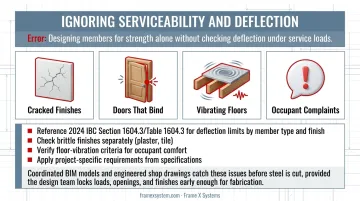
Coordinated BIM models and engineered shop drawings catch these issues before steel is cut—provided the design team locks loads, openings, and finishes early enough for fabrication.
Frequently Asked Questions
What is considered light gauge steel framing?
Light-gauge steel framing uses cold-formed steel members under 1/8" (125 mils) thick, roll-formed into C-studs, tracks, joists, and truss components. Design and installation follow AISI S100, S240, S220, and S202.
Which gauge metal is best for framing?
Gauge depends on load and use: 20-gauge (33 mil) for non-load-bearing partitions, 18- or 16-gauge for load-bearing walls, and 14- or 12-gauge for heavier structural work. Always confirm capacity with load tables or engineering calculations.
Are 20 gauge metal studs load-bearing?
20-gauge (33 mil) studs are typically for non-load-bearing interior partitions. Load-bearing walls generally need 18-gauge (43 mil) or thicker, and structural vs. nonstructural classification also depends on AISI S240 vs. S220 design—not thickness alone.
What is the maximum span of a light-gauge steel truss?
Span depends on configuration, depth, member sizes, loading, and spacing. Residential trusses commonly span 20 to 40 feet; engineered commercial trusses can exceed 60 feet. Each truss needs individual PE design and stamping—no universal limit applies.
What are the common steel stud framing mistakes?
Common mistakes include inadequate lateral bracing, undersized headers, improper fasteners, ignored deflection limits, and poor MEP coordination. Catching these in design prevents costly field corrections.
Where can I find a design manual for cold-formed steel?
Start with AISI S100 for cold-formed steel member design. CFSEI and SFIA publish additional guidance, and manufacturer load tables supply application-specific data.
Final note: Cold-formed steel framing details are not interchangeable templates. Every connection, span, and brace depends on project-specific loads, member properties, and site conditions—use current standards, manufacturer data, and engineering analysis, not generic assumptions.
For coordinated, prefabricated CFS framing with BIM models and stamped structural packages, Frame X Systems provides architect-led design assist, U.S. manufacturing, and sequenced national delivery.