Engineering drawing checks are the critical quality control step that catches these errors before they reach the jobsite. They verify accuracy, completeness, and coordination across disciplines—preventing rework, delays, and safety issues that can derail even well-planned projects.
Key Takeaways
- Drawing checks confirm accuracy, completeness, code compliance, and trade coordination before fabrication
- Strong checks pair engineer review with clash detection and rule-based software verification
- Frequent misses: missing dimensions, conflicting views, incomplete specs, and trade clashes
- One 2024 design-build project avoided $2.2M by resolving 932 preconstruction coordination clashes
What You Need to Check Engineering Drawings
Effective drawing checks need more than a sharp eye. You also need the right reference documents, tools, and project context.
Reference Documents and Standards
Essential references include:
- Building codes: 2024 IBC for most commercial and institutional work; 2024 IRC for residential
- Material standards: ANSI/AISC 360-22 and 303-22 for structural steel; ACI CODE-318-25 and ACI 315R-18 for concrete and reinforcement detailing
- Project specifications: Material grades, finishes, tolerances, and quality requirements for the job
- CAD and BIM standards: Layer conventions, title block formats, and model organization from the company or client
Important: Confirm which code edition your jurisdiction has adopted. The newest published standard may not be enforceable yet, and local amendments often apply.
Review Tools and Software
These tools speed markups, comparisons, and coordination:
- Physical or digital checklists tailored to project type and discipline
- PDF markup software such as Bluebeam Revu or Adobe Acrobat Pro
- CAD viewers to confirm dimensions and geometry without editing source files
- Revision comparison tools that highlight changes between drawing versions
- BIM coordination platforms such as Navisworks or Solibri for clash detection and rule checks
Access and Preconditions
Before beginning a check, ensure you have:
- The complete, current drawing set with all sheets and revisions
- Related discipline drawings (architectural, structural, MEP) for coordination checks
- Project specifications and design criteria documents
- Previous review comments, RFIs, and responses so you track design changes and skip repeat questions
Methods to Check Engineering Drawings
Different projects demand different checking approaches. Most teams use a combination of methods at various project stages.
Method 1: Manual Checklist Review
Description: A systematic review using a standardized checklist covering title blocks, dimensions, specifications, details, and cross-references.
Step-by-Step Process:
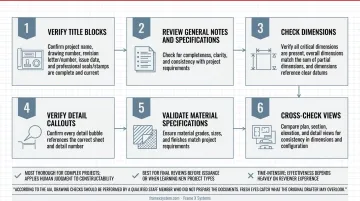
- Verify title blocks: Confirm project name, drawing number, revision letter/number, issue date, and professional seals/stamps are complete and current
- Review general notes and specifications: Check for completeness, clarity, and consistency with project requirements
- Check dimensions: Verify all critical dimensions are present, overall dimensions match the sum of partial dimensions, and dimensions reference clear datums
- Verify detail callouts: Confirm every detail bubble references the correct sheet and detail number
- Validate material specifications: Ensure material grades, sizes, and finishes match project requirements
- Cross-check views: Compare plan, section, elevation, and detail views for consistency in dimensions and configuration
Pros & Cons:
- ✅ Most thorough for complex projects; applies human judgment to constructability
- ✅ Best for final reviews before issuance or when learning new project types
- ❌ Time-intensive; effectiveness depends heavily on reviewer experience
According to the AIA, drawing checks should be performed by a qualified staff member who did not prepare the documents. Fresh eyes catch what the original drafter may overlook.
Method 2: Coordination and Cross-Discipline Review
Description: Focuses on ensuring consistency between engineering disciplines and identifying conflicts before construction begins.
Step-by-Step Process:
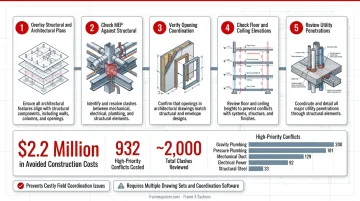
- Overlay structural and architectural plans: Verify column grids, beam locations, and floor elevations align between disciplines
- Check MEP against structural: Identify conflicts where ductwork, conduit, or piping may interfere with structural members
- Verify opening coordination: Confirm door, window, and louver openings match dimensions and locations across architectural and structural drawings
- Check floor and ceiling elevations: Ensure architectural finished floor heights, structural slab levels, and MEP clearances are coordinated
- Review utility penetrations: Identify locations where plumbing stacks, electrical conduits, or mechanical shafts penetrate structural floors or walls
Pros & Cons:
- ✅ Prevents costly field coordination issues and catches interdisciplinary conflicts early
- ✅ Essential for complex projects with multiple trades
- ❌ Requires access to multiple drawing sets and coordination software
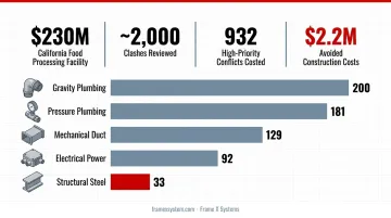
A 2024 DBIA case study on a $230 million California food processing facility documented the team's review of approximately 2,000 clashes. They categorized and costed 932 high-priority conflicts and reported $2.2 million in avoided construction costs.
High-priority clashes included:
- Gravity plumbing: 200
- Pressure plumbing: 181
- Mechanical duct: 129
- Electrical power: 92
- Structural steel: 33
Method 3: Software-Assisted and BIM Coordination Checks
Description: Uses CAD, BIM platforms, or specialized checking tools to automate detection of conflicts, missing information, and standards violations.
Step-by-Step Process:
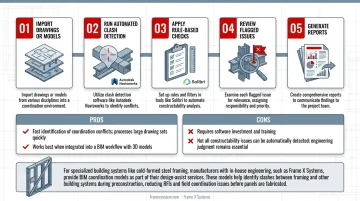
- Import drawings or models: Load architectural, structural, and MEP models into coordination software
- Run automated clash detection: Use tools like Autodesk Navisworks to identify physical conflicts between building systems
- Apply rule-based checks: Configure software like Solibri to verify clearances, accessibility requirements, and other rules
- Review flagged issues: Examine each identified clash or rule violation to determine severity
- Generate reports: Produce coordination reports categorizing issues by discipline, location, and priority
Pros & Cons:
- ✅ Fast identification of coordination conflicts; processes large drawing sets quickly
- ✅ Works best when integrated into a BIM workflow with 3D models
- ❌ Requires software investment and training
- ❌ Not all constructability issues can be automatically detected; engineering judgment remains essential
For specialized building systems like cold-formed steel framing, manufacturers with in-house engineering, such as Frame X Systems, provide BIM coordination models as part of their design-assist services. These models help identify clashes between framing and other building systems during preconstruction, reducing RFIs and field coordination issues before panels are fabricated.
How to Interpret Drawing Check Results
Not every finding requires the same response. Effective interpretation categorizes issues by their impact on construction, cost, schedule, and safety.
Acceptable/No Issues
Criteria:
- All required dimensions, elevations, and notes are present and unambiguous
- Cross-references to details, schedules, and other sheets are correct
- Material specifications match project requirements
- Design meets applicable building codes and standards
- No conflicts exist between plan, section, elevation, and detail views
Action: Proceed to next review stage or issue drawings for construction.
Minor Issues Requiring Clarification
Examples:
- Notes that could be interpreted multiple ways but don't prevent construction
- Dimensions that are technically complete but use unconventional presentation
- Missing non-critical reference details or supplementary information
- Formatting inconsistencies that don't affect constructability
Action: Issue drawings with clarification notes, request information through RFI, or schedule minor revisions before construction starts.
Critical Errors Requiring Correction
Examples:
- Conflicting dimensions between plan and section views
- Missing structural member sizes, connection details, or reinforcement specifications
- Specification conflicts with project requirements or referenced standards
- Building code violations or accessibility non-compliance
- Coordination conflicts between disciplines that prevent installation
- Missing information that makes fabrication or construction impossible
Action: Reject drawings and require corrections before any fabrication or construction proceeds.
Documentation Best Practices
When recording findings:
- Mark locations with cloud markups or highlighted annotations that pinpoint the exact issue
- Cite the applicable code section, standard, or project requirement
- Propose a solution when possible, rather than only flagging the problem
- Log every issue and verify each is resolved before final approval
Interpretation also depends on construction sequencing and fabrication. An error that seems minor on paper (such as a missing bolt pattern) may halt fabrication entirely, while an apparent conflict may be an acceptable field condition.
Common Errors in Engineering Drawing Checks
Certain drawing errors recur across projects. Recognizing these patterns improves checking effectiveness.
Missing or Conflicting Dimensions
Common issues:
- Critical dimensions omitted between control points
- Overall dimensions not matching the sum of partial dimensions
- Conflicting dimensions between plan, section, and detail views
- Dimensions referencing unclear or undefined datums
These errors create field confusion, fabrication delays, and potential rework when installers must guess the designer's intent.
Incomplete or Ambiguous Specifications
Common issues:
- Generic material callouts without grade, ASTM designation, or specification reference
- Finish requirements not specified (for example, "paint" without type or color)
- Welding symbols incomplete or missing critical information like weld size or length
- Fastener types, grades, and spacing undefined
- Notes using "typical" without clearly defining what conditions are typical
Specifications must be specific enough for purchasing agents to order materials and installers to execute work without guessing.
Cross-Reference Errors
Common issues:
- Detail callouts referencing non-existent or incorrect sheet numbers
- Section cuts not matching the actual section drawing location or orientation
- Schedules referencing elements not shown on drawings
- Revision clouds not matching the revision description in the title block
Cross-reference errors force field teams to hunt through drawing sets, leading to delays and potential mistakes.
Standards and Code Compliance Oversights
Common issues:
- Missing accessibility clearances or features required by the ADA or IBC
- Structural member sizes not meeting code-mandated minimums
- Connection details not complying with referenced standards (AISC, ACI)
- Fire-rating requirements not noted for walls, floors, or penetrations
- Seismic detailing omissions in seismic design categories
Code violations discovered during plan review or inspection can halt construction and require expensive redesign.
Coordination Conflicts Between Disciplines
Common issues:
- Structural columns or beams conflicting with architectural door or window openings
- Mechanical ductwork exceeding available structural depth
- Electrical conduit paths blocked by structural members
- Floor elevations not coordinated between architectural and structural drawings
A DBIA case study of 932 high-priority clashes broke the conflicts down by trade:
- 200 gravity plumbing
- 181 pressure plumbing
- 129 mechanical duct
- 92 electrical power
- 61 lighting
- 33 structural steel
Each one was a potential field conflict that would have meant expensive rework if found during construction.
Best Practices for Engineering Drawing Checks
Improve checking effectiveness and efficiency with these practical recommendations.
Use Standardized Checklists
- Develop project-type-specific checklists covering common issues for residential, commercial, institutional, or industrial projects
- Update checklists based on lessons learned from previous projects
- Ensure checkers understand the reasoning behind each item. Mechanical completion without understanding reduces effectiveness
Implement Multi-Stage Review
According to the U.S. Army Corps of Engineers, every graphic and plan should receive an independent check with critical dimensions, elevations, notes, and references marked, initialed, and dated. A comprehensive review process includes:
- Self-checks by the originating engineer or designer
- Peer reviews by another qualified team member
- Final QA reviews by senior staff before client submission
- Cross-discipline coordination reviews at key milestones (30%, 60%, 90% completion)
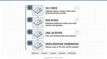
Preserve checkprints, comments, responses, resolutions, and certifications to document the review process.
Use Technology Appropriately
- PDF comparison tools like Bluebeam's Compare Documents verify only intended changes occurred between revisions
- BIM coordination software for complex multi-discipline projects to automate clash detection
- Databases of common errors and project-specific checking points
- Software limits: tools cannot replace engineering judgment on constructability, design intent, or code interpretation
Effective checking is collaborative. Specialized manufacturers that offer design-assist services (for example, cold-formed steel framing suppliers with in-house engineering) can flag constructability issues early. Their preconstruction coordination, BIM models, and engineered shop drawings surface problems before drawings reach the field.
Frame X Systems provides architect-led design assistance, BIM coordination models, and project-specific shop drawings during preconstruction. That work resolves conflicts between framing and architectural, structural, and MEP systems before fabrication begins.
Frequently Asked Questions
What is the difference between a drawing check and a drawing review?
A drawing check verifies technical accuracy, completeness, and standards compliance (dimensions, cross-references, and codes). A drawing review is broader: design intent, constructability, value engineering, and stakeholder feedback at different project stages.
Who is responsible for checking engineering drawings in construction projects?
The engineer of record is ultimately responsible for drawing accuracy. Strong projects still use layered checks: drafter self-checks, peer and senior QA reviews, plus coordination with architects and other disciplines before construction.
What are the most common errors found in structural engineering drawings?
Common errors include missing or conflicting dimensions, incomplete connection or weld details, material callouts that don't match calculations, clashes with architectural drawings, and missing code notes (fire ratings, seismic detailing).
How long should an engineering drawing check take?
It depends on complexity, checker experience, and review depth. Straightforward plans often take 15–30 minutes per sheet; complex or coordination-heavy sheets can take 1–2 hours each.
What software tools are most helpful for checking engineering drawings?
Most teams rely on PDF markup tools (Bluebeam, Adobe Acrobat), CAD viewers for measurements, and BIM platforms like Navisworks or Solibri for clash detection. Revision-comparison tools help track changes between drawing versions.
Can drawing checks be automated with AI or software?
Software can automate clash detection, formatting checks, and cross-reference validation. Constructability, design intent, and code interpretation still need engineering judgment, so the best approach pairs automation with human review.