This guide covers when load-bearing walls are necessary, structural requirements, step-by-step framing procedures, critical parameters that affect results, and common mistakes to avoid.
Key Takeaways
- Size headers correctly, space studs at 16" or 24" on-center, and use double top plates to carry and distribute loads
- Meet IRC rules with graded lumber, engineered headers on wide openings, and the specified nailing schedule
- Most failures stem from undersized headers, incorrect stud spacing, poor bearing surfaces, or omitting king/jack studs
- Confirm layout, bearing surfaces, and structural specs on paper before you raise the wall
How to Frame a Load-Bearing Wall
Framing a load-bearing wall follows a fixed sequence: lay out the plates, assemble the frame flat, raise and brace it, then install the double top plate and connections. Work to the 2021 IRC and confirm every mark before you cut.
Step 1: Lay Out the Top and Bottom Plates
Start by cutting matching top and bottom plates from straight, dry lumber. Place them side by side with ends flush, then mark both plates simultaneously to ensure alignment.
Mark stud locations:
- Begin with the first stud edge at 15¼" to align with standard 4×8 sheathing
- Continue marking at 16" or 24" on-center spacing per 2021 IRC Table R602.3(5)
- Use precise measurements for rough openings, including king stud, jack stud, and cripple positions
- Mark corners, T-intersections, and partition hits for extra studs or backup framing
Layout accuracy matters: Errors here multiply when the wall is raised and sheathed, so verify measurements twice before cutting.
Step 2: Assemble Wall Frame Components
Build the wall flat on the subfloor or a clean, level surface. This lets you verify square and alignment before raising.
Install studs and rough openings:
- Cut full-length studs and fasten them between plates at marked on-center locations
- Frame openings by installing full-height king studs, then jack studs (trimmers) inside them to support the header
- Build headers using appropriately sized lumber per IRC span tables, adding ½" plywood spacers to match 3½" wall thickness
- Secure headers with 16d common nails at 16" on-center along each edge
- Install cripple studs above headers and below window sills to maintain on-center spacing and provide sheathing nailing
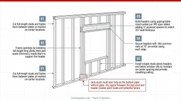
Critical detail: Jack studs must bear fully on the bottom plate without gaps. Any space between the jack stud and header creates point loads and potential failure.
Step 3: Raise and Secure the Wall
Never attempt to raise a wall alone. Recruit at least 2-3 crew members for standard 8-foot walls; larger or sheathed walls require more hands or mechanical assistance.
Raising procedure:
- Position the wall assembly so the bottom plate aligns with its final location
- Lift the top plate gradually, walking the wall upward while checking for stability
- Secure the bottom plate to the subfloor or sill plate using 16d nails or structural screws every 16"
- Install temporary diagonal bracing (2×4s at 45-degree angles) immediately to hold the wall plumb until permanent sheathing is applied
Safety note: NIOSH guidance highlights that manual wall raising creates high back and shoulder forces. Use a competent lift plan, adequate crew size, or mechanical wall jacks for heavy sections.
Step 4: Install Double Top Plate and Make Connections
The double top plate (cap plate) ties walls together structurally and distributes loads between studs. The 2021 IRC requires double top plates for conventional wood stud bearing walls.
Installation requirements:
- Overlap wall intersections by at least 48" to tie walls together
- Offset end joints in the double plate by at least 24" from joints in the single top plate below
- Fasten laps with eight 16d common nails on each side of the joint
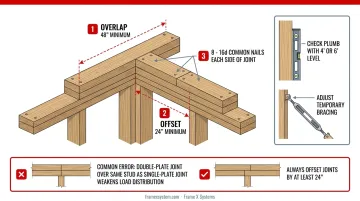
Before final fastening:
- Check plumb at multiple points with a 4- or 6-foot level
- Adjust temporary bracing to straighten the wall
Common error: Placing double-plate joints over the same stud location as single-plate joints weakens the load distribution. Always offset joints by at least 24".
When Should You Frame a Load-Bearing Wall?
Not every wall in a building needs to be load-bearing. Knowing when you need structural support versus a simple partition cuts material, labor, and engineering spend.
Load-bearing walls are required when:
- Exterior perimeter walls that carry roof or floor loads above
- Walls running perpendicular to floor or ceiling joists and supporting their ends
- Stacked walls sitting directly under another load-bearing wall in multi-story work
- Supports for beam ends, concentrated point loads, or engineered roof trusses
Non-load-bearing partitions are sufficient when:
- Runs parallel to joists with no structural loads above
- Divides interior space already carried by other structural elements
- Acts only as a room divider where the open plan already has adequate support
Important distinction: A wall perpendicular to joists may be load-bearing—but orientation alone is not proof. Parallel walls can still carry beams or point loads. Always verify the load path on structural plans, or consult an engineer, before modifying any existing wall.
What You Need Before Framing a Load-Bearing Wall
Proper preparation and the right materials on-site directly impact structural integrity and code compliance. Missing a critical element during assembly means stopping work, losing time, and potentially compromising the build.
Materials and Lumber Requirements
Studs:
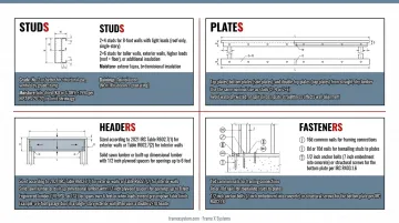
- 2×4 studs for 8-foot walls with light loads (roof only, single-story)
- 2×6 studs for taller walls, exterior walls, higher loads (roof + floor), or additional insulation
- Grade: No. 2 or better for structural use, verified by grade stamp
- Moisture: kiln-dried (KD or S-DRY, ≤19% per NIST PS 20-20) to limit shrinkage
Plates:
- Top plates, bottom plates (sole plates), and double top plates (cap plates) from straight, dry lumber
- Use the same nominal size as studs (2×4 or 2×6)
- Avoid warped, twisted, or split pieces—plate straightness affects wall alignment
Headers:
- Sized according to 2021 IRC Table R602.7(1) for exterior walls or Table R602.7(2) for interior walls
- Solid sawn lumber or built-up dimensional lumber with ½" plywood spacers for openings up to 6 feet
- Engineered lumber (LVL, PSL, or LSL) for spans over 6 feet or when loads exceed prescriptive table limits
- Example: a 6-foot garage door in a single-story exterior wall often uses a double 2×10 header
Fasteners:
- 16d common nails for framing connections
- 8d or 10d nails for toenailing studs to plates
- ½" anchor bolts (7" embedment into concrete) or structural screws for the bottom plate per IRC R403.1.6
Tools and Equipment
Layout and cutting:
- Tape measure, chalk line, framing square, speed square
- Circular saw or miter saw for cutting lumber to length
- Pencils and markers for clear stud marking
Assembly and verification:
- Framing nailer (pneumatic or cordless) or hammer
- 4-foot and 6-foot levels for plumb checking
- Temporary wall bracing materials (2×4 braces, stakes)
- Sawhorses or staging for assembly
Plan crew size before you raise: at least 2–3 people for an 8-foot wall, and more for longer or sheathed sections.
Code Knowledge and Structural Plans
Required documentation:
- Building plans showing load-bearing wall locations, header sizes, and structural specifications
- Plans stamped by engineer or architect where jurisdiction statutes require it
- Familiarity with local codes and 2021 IRC wall-construction requirements (stud spacing, headers, nailing, bearing plates)
Permits and inspections:
- Building permits required per 2021 IRC R105.1 for constructing or altering a building
- Framing inspection scheduled before covering with sheathing or drywall per IRC R109.1.4
Key Parameters That Affect Results When Framing a Load-Bearing Wall
Structural integrity and code compliance depend on a few variables you control during framing: stud spacing, headers, bearing, and lumber quality. Mistakes in any of them can cause sagging, cracking, or structural failure.
Stud Spacing and On-Center Layout
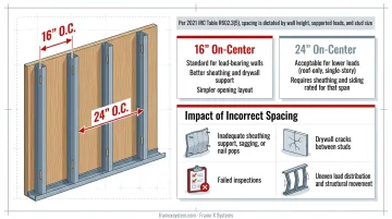
Standard spacing is 16" or 24" on-center, dictated by 2021 IRC Table R602.3(5) based on wall height, supported loads, and stud size.
Spacing guidelines:
- 16" on-center: Standard for load-bearing walls; better sheathing and drywall support, simpler opening layout
- 24" on-center: Acceptable for lower loads (roof-only, single-story) when sheathing and siding are rated for that span
Impact of incorrect spacing:
- Inadequate sheathing support, sagging, or nail pops
- Drywall cracks between studs
- Failed inspections
- Uneven load distribution and structural movement
Header Size and Span Capacity
Headers must be sized according to IRC span tables based on opening width, load above (roof only vs. roof + floor), and species/grade of lumber.
Sizing rules:
- For openings under 4 feet: built-up dimensional lumber (double 2×6, 2×8, etc.) with ½" plywood spacers typically suffices
- For openings over 4 feet: engineered lumber (LVL, LSL, PSL) is often required to meet span and deflection limits
- Use manufacturer sizing tools or IRC tables to confirm capacity
Impact of undersized headers:
- Sagging as the header deflects under load
- Cracks in drywall, door frames, and window trim
- Structural failure in extreme cases
- Failed inspections and costly rework
Critical detail: If the header top lacks perpendicular lateral bracing, tabulated spans for 2×8, 2×10, and 2×12 headers must be multiplied by 0.70—or the member must be professionally designed.
Bearing Surface and Load Transfer
Bottom plates must rest on properly prepared bearing surfaces—foundation walls, floor beams, or structural subfloors capable of supporting the loads above.
Bearing requirements:
- Bottom plates require continuous bearing across their length
- Jack studs under headers must bear fully on the bottom plate with no gaps
- Foundation sills need ½" anchor bolts embedded 7" into concrete, spaced maximum 6 feet on-center, with at least two bolts per plate
Impact of poor bearing contact:
- Point loads that crush wood fibers
- Uneven settling and structural movement
- Header failure from inadequate support
- Progressive structural problems over time
Lumber Quality and Moisture Content
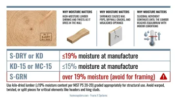
Use kiln-dried lumber (≤19% moisture content per NIST PS 20-20) graded appropriately for structural use. Avoid warped, twisted, or split pieces for critical elements like headers and king studs.
Why moisture matters:
- High-moisture lumber shrinks and twists as it dries in the wall
- Shrinkage causes nail pops, drywall cracks, and misaligned openings
- Seasonal movement continues until the lumber reaches equilibrium with indoor conditions
Moisture designations on grade stamps:
- S-DRY or KD: ≤19% moisture at manufacture
- KD-15 or MC-15: ≤15% moisture at manufacture
- S-GRN: over 19% moisture (avoid for framing)
Common Mistakes When Framing a Load-Bearing Wall
Most framing failures stem from skipping structural elements, using undersized materials, or ignoring code-required details. Here's what to avoid:
Using single top plates instead of double plates:
- The double top plate distributes loads between studs and ties walls together at intersections
- Single plates are permitted only when every condition in IRC R602.3.2 is met. That exception is rare and requires aligned loads plus prescribed ties
- Default to double plates for load-bearing walls
Installing undersized headers:
- Selecting headers by opening width alone ignores load above, building width, snow load, and species
- Skipping engineered lumber on wide openings leads to excessive deflection
- Always verify header size against the applicable IRC table or manufacturer data
Omitting jack studs or providing inadequate bearing:
- Jack studs (trimmers) transfer the header load to the bottom plate and foundation
- Headers need one or more jack studs at each end per the IRC table or an approved framing anchor
- Gaps between jack studs and headers create point loads and structural failure
Neglecting cripple studs:
- Cripple studs above headers and below window sills maintain on-center spacing for sheathing
- Skipping them creates weak points and unsupported sheathing edges
- Install cripples to match the layout grid, even if the opening disrupts regular stud spacing
Skipping temporary bracing:
- Walls shift out of plumb before sheathing is applied
- Attach adjustable braces to the top plate about every 8 feet. Plumb the corners, then straighten the run with a stringline before final fastening
- Leave bracing in place until permanent sheathing or other lateral support is installed
Alternatives to Traditional Wood-Framed Load-Bearing Walls
While dimensional lumber framing is most common in residential construction, other structural systems may be more appropriate depending on project requirements, building type, and design goals.
Cold-Formed Steel Framing
When it's better:
- Commercial buildings requiring fire resistance and noncombustible construction
- Projects over 3-4 stories where dimensional stability is critical
- Areas with termite concerns or high moisture exposure
- Tight construction schedules with complex coordination between trades
Key trade-offs:
- Requires different tools (screw guns, metal snips) and fasteners (self-drilling screws)
- Higher material cost but reduced callbacks from warping, shrinking, or rot
- Specialized labor skills: verify local trade familiarity before committing
- Excellent moisture and fire resistance, but steel conducts heat/cold (thermal bridging requires deliberate insulation strategy)
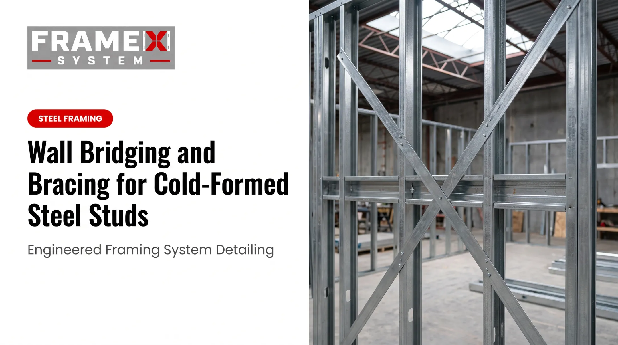
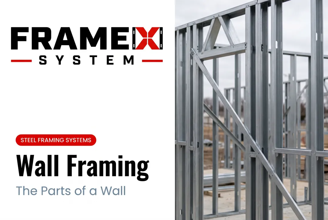
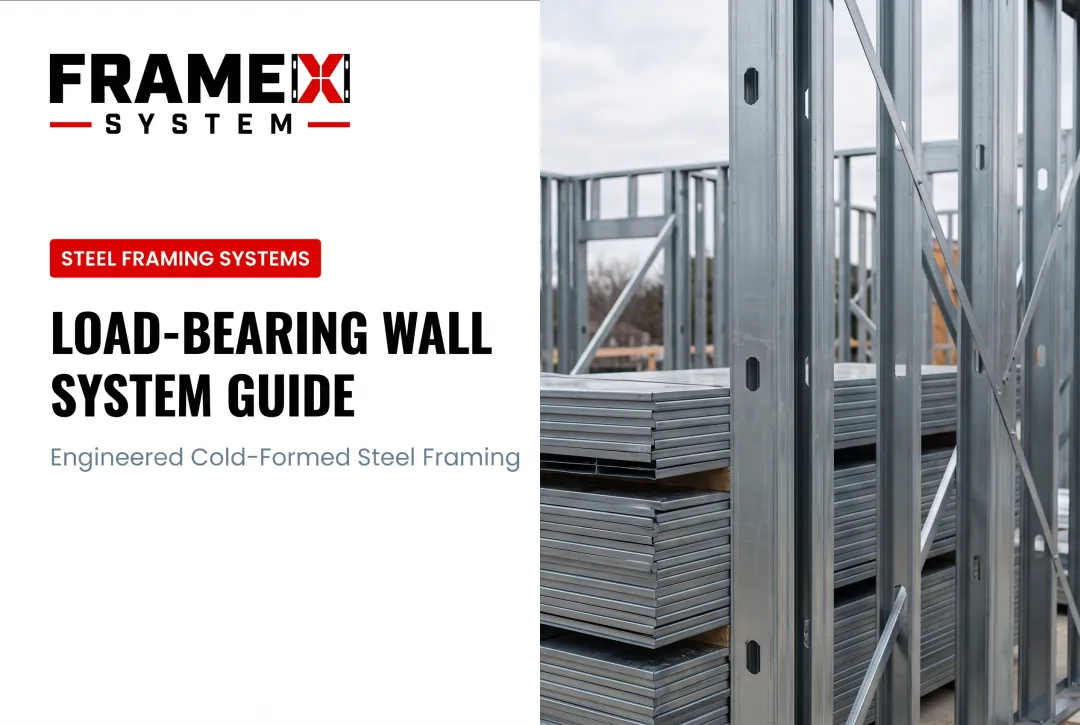
Frame X Systems example: For projects that need installation-ready steel framing, Frame X Systems manufactures cold-formed steel load-bearing wall panels, trusses, and structural assemblies in the USA. Assemblies use galvanized light-gauge steel studs with horizontal tracks and diagonal reinforcements.
Packages ship with BIM-coordinated shop drawings, stamped structural documents, and sequenced installation docs. Panels are labeled and bundled by location to cut field labor, RFIs, and on-site coordination. With 28+ years of construction experience and 150+ projects designed, FrameX supplies architects, contractors, and developers nationwide.
Structural Insulated Panels (SIPs)
When it's better:
- Energy-efficient construction prioritizing insulation performance
- Faster build times with reduced on-site labor
- Projects where labor availability is limited or expensive
- Buildings seeking tight thermal envelopes and minimal air infiltration
Key trade-offs:
- Limited flexibility for on-site changes—shop drawings must be precise
- Requires crane for panel installation on most projects
- Higher upfront cost offset by faster enclosure and reduced HVAC loads
- Electrical and plumbing runs require advance planning; harder to modify after installation
Engineered Wall Systems and Prefabricated Panels
When it's better:
- Production housing or multifamily developments with repeating floor plans
- Tight construction schedules where weather delays are costly
- Projects requiring consistent quality and factory-controlled tolerances
- Job-site conditions that limit on-site fabrication (urban sites, restricted access)
Key trade-offs:
- Requires advance planning and lead time for engineering and fabrication
- Limited site flexibility—changes after manufacturing are expensive
- Higher initial cost but faster installation, reduced field labor, and fewer callbacks
- Factory-built quality control ensures code compliance and dimensional accuracy
Conclusion
Framing load-bearing walls correctly requires understanding structural principles, using properly sized materials, and following code requirements for stud spacing, header sizing, and load transfer. Most failures stem from undersized headers, improper bearing conditions, or skipping critical elements like jack studs and double top plates.
Before you cover the framing, lock in these essentials:
- Lay out openings and studs accurately
- Verify header spans against IRC tables
- Use kiln-dried lumber graded for structural use
- Schedule inspections before closing the wall
Done right, a load-bearing wall delivers decades of reliable service with minimal maintenance or callbacks.
Frequently Asked Questions
How far apart should studs be on a load-bearing wall?
Standard spacing is 16" or 24" on-center per 2021 IRC Table R602.3(5), with 16" most common on load-bearing walls. Allowed spacing depends on stud size, wall height, and supported loads.
Can a 2×4 stud wall be load-bearing?
Yes—for single-story construction, standard 8-foot heights, and typical residential roof-only loads. Use 2×6 for taller walls, higher loads (roof + floor), two-story construction, or when energy code needs a deeper insulation cavity.
How thick does a load-bearing wall need to be?
Standard thickness is 3½" (2×4 framing) or 5½" (2×6 framing). Thickness follows height, loads, insulation, and energy code—not load-bearing status alone—while capacity comes from stud spacing, header size, and material grade.
How big can an opening be in a load-bearing wall?
Opening size is limited by header span capacity per IRC tables—typically up to 8–10 feet for double 2×12 headers under specific residential loads. Larger openings need engineered lumber (LVL, PSL, LSL) or steel beams sized by a PE against actual load, building width, and species/grade.
Can interior walls be load-bearing?
Yes. Interior walls often carry load when they run perpendicular to joists, sit under upper-floor bearing walls, or support beam ends. Never assume an interior wall is non-structural; verify the load path on plans or consult an engineer before modifying it.
How is a load-bearing wall framed?
Load-bearing walls use a bottom plate, studs at 16" or 24" on-center, and double top plates. Headers span openings on jack studs, with full-height king studs on each side. Cripple studs keep on-center spacing above and below openings.