Key Takeaways
- Cold-formed steel purlins transfer roof loads and must pass combined bending, shear, buckling, and deflection checks per AISI S100
- Design must cover purlin type, grade, load combinations, panel bracing, and connection capacity for gravity and uplift
- Serviceability often governs sizing—IBC 2024 limits are typically L/150 live and L/60 total for formed-metal roofing
- Roof-panel attachment and sag rods develop full purlin capacity and prevent lateral-torsional instability
- Coordinated engineering, BIM, and fabrication resolve constructability before install, cutting field labor and risk
What is a Cold-Formed Steel Roof Purlin?
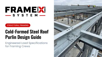
A roof purlin is a horizontal structural member that spans between primary framing elements such as trusses, rigid frames, or rafters. It supports roof decking and transfers gravity and lateral loads to the main structure.
Cold-formed steel purlins are roll-formed from thin steel sheets at ambient temperature, typically 12–20 gauge (about 0.054 to 0.120 inches thick). That process yields a high strength-to-weight ratio, so CFS purlins stay economical for long spans and repetitive framing layouts.
Typical purlin systems consist of:
- Continuous spans with lapped or nested connections centered over support points
- Lateral stability from roof panel attachment to the compression flange
- Discrete bracing such as sag rods or anti-roll clips to control torsional instability
- Clips, cleats, or bolted connections to primary framing members
This configuration gives engineers greater spanning capacity and more predictable behavior than simple-span members. Connection details and bracing assumptions still need careful attention.
Types and Components of Roof Purlin Systems
Purlin Cross-Section Types
C-Section Purlins
C-sections feature a uniform channel shape with parallel flanges and are economical to manufacture. They suit lower roof slopes, where gravity load aligns closely with the web axis, and are a common choice when simplicity and cost matter most. C-purlins can be installed singly or back-to-back for increased capacity.
Z-Section Purlins
Z-sections have a point-symmetric profile that allows for nested lapping at supports, creating efficient continuous-span configurations. Their shape aligns better with the principal load axes on sloped roofs, reducing biaxial bending and improving structural performance under combined gravity and lateral loads. Z-purlins are frequently specified as the standard roof secondary framing member in pre-engineered metal building systems.
Material Components and Properties
Cold-formed steel purlins are typically specified using one of two coating systems:
- ASTM A653: Hot-dip zinc-coated (galvanized) or zinc-iron alloy-coated (galvannealed) sheet, offering corrosion protection for standard environments
- ASTM A792: 55% aluminum-zinc alloy-coated sheet (commonly called Galvalume), used where superior corrosion resistance or heat resistance is required
Yield strengths vary by grade and cold-forming process, commonly ranging from 33 to 55 ksi (230 to 380 MPa). Cold-forming can raise base sheet strength, but capacity still depends on effective section properties. Design per AISI S100 must account for local, distortional, and lateral-torsional buckling in thin-walled sections.
Purlin System Accessories
Essential components that complete a purlin system include:
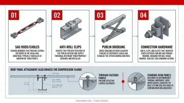
- Sag rods/cables: Tension members that provide lateral restraint in the weak-axis direction, typically installed at midspan or third points
- Anti-roll clips: Devices that prevent rotation of the purlin section and supply torsional restraint when properly designed and installed
- Purlin bridging: Cross-bracing between adjacent purlins to distribute loads and stabilize the system during erection
- Connection hardware: Bolts, clips, and cleats that transfer forces between purlins and primary framing, designed for bolt shear, bearing, tear-out, and combined actions
Roof panel attachment also braces the compression flange. Through-fastened panels provide effective lateral restraint. Standing-seam panels, designed to accommodate thermal movement, need more careful analysis or base testing per AISI S908 to confirm bracing adequacy.
Key Design Considerations for Cold-Formed Steel Purlins
Successful purlin design balances structural capacity, serviceability, material economy, and installation practicality. The following seven factors are interrelated and must be evaluated together.
Span and Spacing Requirements
Span (distance between supports) and spacing (purlin-to-purlin distance) directly influence member size and system cost. Manufacturer literature shows products capable of spanning up to 32 feet and, subject to loading, potentially 40 feet for deeper sections. Spacing typically ranges from 2 to 5.5 feet, governed by roof panel capacity and project-specific loading.
The trade-off is straightforward: fewer, larger purlins at wider spacing reduce purlin material and labor but require heavier, more expensive roof panels. Conversely, closer spacing allows lighter panels but increases purlin count, connections, and erection time. Optimizing this balance requires coordination between structural and envelope design.
Load Combinations and Critical Loading
Purlins must resist multiple load types:
- Dead loads: Roofing, insulation, mechanical equipment, and the purlin's self-weight
- Live loads: Maintenance and construction access
- Snow loads: Uniform accumulation and drift patterns per ASCE 7
- Wind loads: Downward pressure and uplift suction, often the governing case for connection design
On sloped roofs, applied loads resolve into components parallel and perpendicular to the purlin web, creating biaxial bending and torsion. This makes load-direction sensitivity a critical design consideration.
Continuous spans produce moment reversal at interior supports, requiring capacity checks at both positive- and negative-bending locations. ASCE 7 load combinations (either ASD or LRFD) must be applied per the jurisdiction's adopted code edition.
Structural Capacity Checks
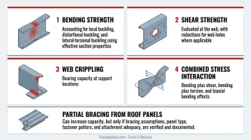
Cold-formed steel design per AISI S100 differs from hot-rolled steel. Engineers must verify multiple limit states:
- Bending strength: Accounting for local buckling, distortional buckling, and lateral-torsional buckling using effective section properties
- Shear strength: Evaluated at the web, with reductions for web holes where applicable
- Web crippling: Bearing capacity at support locations
- Combined stress interaction: Bending plus shear, bending plus torsion, and biaxial bending effects
Thin-walled instabilities dominate capacity calculations. Partial bracing from roof panels can increase capacity, but only if the bracing assumptions (panel type, fastener pattern, and attachment adequacy) are verified and documented.
Deflection and Serviceability Limits
Deflection often controls purlin size more than strength, particularly for longer spans and lighter loads. IBC 2024 Table 1604.3 specifies L/150 for live-load deflection and L/60 for total-load deflection of secondary roof members supporting formed-metal roofing. These limits are more relaxed than the L/180 and L/120 values sometimes cited generically, so confirming the locally adopted code edition is essential.
For sloped roofs, purlins experience biaxial deflection: both vertical (strong axis) and lateral (weak axis). Sag rods reduce weak-axis deflection, but their effectiveness depends on proper spacing, tensioning, and load-path continuity. Engineers must check both axes and ensure that total deflection does not impair roof panel performance or create ponding conditions.
Connection and Continuity Details
Most purlin systems use continuous-span configurations with lapped or nested connections at supports. Lap length, bolt spacing, edge distance, and connection stiffness all influence load distribution and moment transfer. AISI S100 requires checks for:
- Bolt spacing (Section J3.1)
- Edge and end distance (J3.2)
- Bearing (J3.3)
- Bolt shear and tension (J3.4)
- Rupture, block shear, pull-out, pull-over, and combined actions (J4 and J6)
A poorly detailed connection can erase the benefits of continuity, forcing the system to behave as a series of simple spans with reduced capacity and increased deflection. Connection design must also address uplift forces from wind suction, ensuring adequate resistance to pull-out and pull-over failures.
Lateral and Torsional Restraint
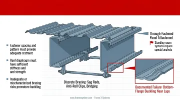
Purlin capacity depends heavily on bracing. Roof panels typically brace the top flange through fastener attachment, significantly increasing lateral-torsional buckling resistance. However, this assumption is valid only when:
- Through-fastened panels are used (standing-seam systems require special analysis)
- Fastener spacing and pattern provide adequate restraint
- The roof diaphragm has sufficient stiffness and strength
Discrete bracing—sag rods, anti-roll clips, or bridging—provides additional torsional restraint and weak-axis support. If bracing is inadequate or mischaracterized, the purlin may buckle prematurely near braces or at lapped connections. Documented failure cases include bottom-flange local buckling near laps and reduced capacity from inadequate restraint systems.
Installation and Constructability
Design must account for real-world installation conditions:
- Handling limitations during delivery and erection
- Temporary bracing requirements before roof panels are attached
- Tolerance for field adjustment without compromising capacity
- Coordination between purlin installation and roof panel attachment sequence
Pre-punched, labeled, and sequenced delivery systems reduce field measuring, cutting, and errors, improving safety and schedule predictability. Early coordination with general contractors and erectors confirms the design is buildable as detailed and cuts field rework.
Design Process and Calculations
Purlin design follows a systematic workflow from initial load determination through final documentation. Each step builds on the previous one, and iteration is common as trial sections are refined.
Establish Design Parameters
Begin by gathering project-specific information:
- Building location, applicable codes (IBC, ASCE 7, AISI S100 editions adopted by jurisdiction)
- Roof geometry: slope, bay spacing, overhang conditions, primary framing type (trusses, rigid frames)
- Roof covering and insulation assembly details, which affect dead load and bracing assumptions
- Special loads such as rooftop equipment, solar panels, or concentrated maintenance loads
Determine design loads using the jurisdiction's adopted ASCE 7 edition. Calculate ground and roof snow loads, identify wind speed and exposure category, and establish applicable importance factors.
Calculate Load Effects
Resolve applied loads into purlin axes, accounting for roof slope. Form load combinations per ASCE 7 (ASD or LRFD) and calculate maximum moment, shear, and reaction forces at critical locations. For continuous spans, analyze both positive and negative bending regions and identify the governing load case.
Sloped-roof purlins experience biaxial bending because gravity loads act in both the strong and weak axes. Both components must be included for accurate capacity prediction.
Select Trial Section and Check Capacity
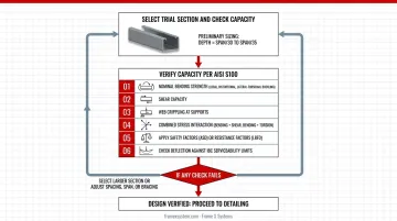
Select a trial purlin size from manufacturer catalogs or use preliminary sizing rules (common practice suggests depth approximately span/30 to span/35). Verify capacity per AISI S100:
- Calculate nominal bending strength considering local, distortional, and lateral-torsional buckling modes
- Check shear capacity
- Evaluate web crippling at supports
- Verify combined stress interaction (bending plus shear, bending plus torsion)
- Apply appropriate safety factors (ASD) or resistance factors (LRFD)
- Check deflection against IBC serviceability limits
If any check fails, select a larger section or adjust spacing, span, or bracing assumptions and repeat.
Verify Bracing and Connection Details
Confirm that assumed bracing conditions (roof panel type, fastener pattern, sag rod size and spacing) can develop the calculated purlin capacity. Design connections for gravity loads and uplift, checking bolt capacity, bearing, edge distance, and tear-out resistance.
Document bracing forces and verify anchorage into primary framing and load paths through the roof diaphragm per AISI S100 Section I6.4.
Prepare Construction Documents
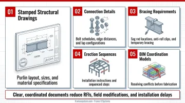
Installation-ready purlin systems require complete documentation:
- Stamped structural drawings showing purlin layout, sizes, and material specifications
- Connection details with bolt schedules, edge distances, and lap configurations
- Bracing requirements including sag rod locations, anti-roll clip specifications, and temporary bracing
- Erection sequences and installation instructions
- BIM coordination models to resolve conflicts with other building systems before fabrication
Clear, coordinated documents reduce RFIs, field modifications, and installation delays.
How Frame X Systems Can Help
Frame X Systems brings an architect-led approach to cold-formed steel framing, covering structural design through delivery of installation-ready systems.
With 28+ years of construction experience and 150+ projects designed, FrameX resolves constructability challenges before components reach the jobsite. That early coordination closes the gaps that often cause purlin installation issues and project delays.
FrameX provides fully coordinated framing packages—built for roof and wall systems alike—that include:
- Project-specific engineered shop drawings and stamped structural packages prepared by professional engineers
- BIM coordination models that integrate framing with architectural, structural, and MEP systems to identify clashes early
- Precision-manufactured cold-formed steel components, including truss panels and structural framing assemblies, made to exact specs in a USA facility
- Pre-punched, labeled, and sequenced components delivered in installation order to reduce field labor and minimize errors
- Preconstruction collaboration with architects, contractors, and engineers to optimize layouts, connections, and coordination
Nationwide delivery and end-to-end service, from design assist through manufacturing and shipping, ensure framing systems arrive installation-ready with full documentation and engineering support. The same workflow cuts material waste, shortens schedules, and gives commercial, institutional, residential, and custom projects predictable field performance across the United States.
Conclusion
Cold-formed steel purlin design works when you treat the roof as a system, not a catalog pick. Capacity depends on more than one load-table selection:
- Structural capacity and material grade
- Bracing systems and continuity effects
- Connection details and installation requirements
Load tables alone miss the bracing assumptions and system behavior that control field performance. The strongest purlin layouts balance strength with constructability through early collaboration among structural engineers, architects, and fabricators in preconstruction.
When loads change—or when you evaluate an existing structure for new equipment or code compliance—re-verify purlin capacity. Modern AISI S100 methods and updated load requirements often show older systems fall short. Catching that early avoids costly retrofits and unsafe conditions.
Frequently Asked Questions
What is a purlin in a roof?
A roof purlin is a horizontal structural beam that spans between primary framing members such as trusses or rigid frame rafters. It supports the roof covering and transfers loads to the main structure as a secondary framing element working with the roof panels.
What's stronger, Z or C purlin?
Neither is inherently stronger. Capacity depends on section dimensions, material grade, span, loading, continuity, and bracing. Z-purlins often perform better on sloped roofs; C-purlins can be more economical for low-slope work—compare specific sections under actual project loads.
How far can a purlin span without support?
Maximum span depends on purlin size, material grade, roof loads, deflection limits, bracing, and continuous vs. simple-span layout. Manufacturer literature shows spans around 32 feet, and up to 40 feet for deeper sections under lighter loads. Use project-specific engineering rather than rule-of-thumb values.
How far apart do you put purlins on a roof?
Purlin spacing typically ranges from about 2 to 5.5 feet on center, set by roof panel capacity, project loads, and the cost trade-off between purlins and panels. Wider spacing cuts purlin material but needs heavier panels, so optimal spacing comes from coordinated design of both systems.
How strong is cold-formed steel?
Cold-formed steel purlins commonly have yield strengths from 33 to 55 ksi (230 to 380 MPa), depending on base sheet grade and cold-forming effects. Structural capacity must follow AISI S100 methods that account for local, distortional, and lateral-torsional buckling in thin-walled sections.
Do purlins sit on top of trusses?
Yes. Purlins typically sit on the top chord of roof trusses or rigid-frame rafters and connect with clips, bolts, or welds. The connection must transfer gravity and wind uplift safely for the primary structure type.