The decision to use scissor trusses affects far more than aesthetics. It influences structural engineering requirements, material costs, installation complexity, bearing design, insulation strategy, and long-term building performance. This guide walks through the key considerations that architects, contractors, and developers must address when specifying scissor trusses.
Key Takeaways
- Angled bottom chords create vaulted ceilings—unlike standard flat-bottom trusses
- Design loads and geometry are project-specific and need sealed structural drawings before fabrication
- Bearings must handle horizontal thrust (up to 1.25 in. per TPI) via wall design or specialty connectors
- Cold-formed steel scissor trusses offer longer spans, dimensional consistency, and resistance to moisture and rot
- Early coordination with the truss designer, engineer, and fabricator improves span performance and field fit
What is a Scissor Truss?
A scissor truss is a structural roof truss characterized by its inverted-V bottom chords that slope upward from the supports to meet near the center, creating a vaulted or cathedral ceiling effect below. Unlike conventional trusses with flat bottom chords, the angled configuration eliminates the need for separate ceiling framing while providing both roof support and interior ceiling definition.
Scissor trusses are built in wood or cold-formed steel. Under the 2024 International Residential Code (IRC), metal-plate-connected wood scissor trusses must comply with ANSI/TPI 1-2022, the national design standard for that system. Regardless of material, engineered scissor trusses require sealed design drawings with project-specific specifications.
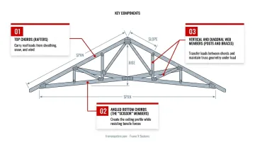
Key Components
Scissor trusses consist of three primary structural members:
- Top chords (rafters) — carry roof loads from sheathing, snow, and wind
- Angled bottom chords (the "scissor" members) — create the ceiling profile while resisting tensile forces
- Vertical and diagonal web members (posts and braces) — transfer loads between chords and maintain truss geometry under load
Benefits and Limitations of Scissor Trusses
Scissor trusses deliver vaulted interiors and open floor plans that flat-bottom trusses cannot match. Those gains come with trade-offs in attic space, eave detailing, and bearing design.
Advantages:
- Creates vaulted or cathedral ceilings without interior load-bearing walls in many layouts
- Combines roof and ceiling framing in one engineered system
- Distributes loads efficiently through triangulated geometry
- Reduces field errors with factory fabrication and sealed structural drawings
- Speeds installation through pre-engineered packages
- Supports varied pitches, large spans, and complex profiles, including curves
Those strengths matter most when the project values interior volume over attic storage.
Limitations and detailing demands:
- Limits attic access and storage compared with flat-bottom trusses
- Complicates insulation and ventilation at tight eaves
- Requires the Building Designer to accept horizontal deflection at bearings, or to handle it with special wall provisions and connectors
- Depends on correct vapor barriers and insulation detailing for moisture control
- Requires tighter HVAC, electrical, and systems coordination because attic volume is reduced
- Restricts access to roof sheathing from below for future maintenance
Scissor trusses are not a universal solution. They work best when architects and engineers align early on bearing design, building-system integration, and code-required insulation and ventilation clearances.
Structural Design Requirements
Scissor trusses are engineered systems, not prescriptive assemblies. Each project requires sealed truss design drawings prepared by a structural engineer or qualified truss manufacturer, meeting the requirements of the locally adopted building code.
Governing Standards
The 2024 IRC references ANSI/TPI 1-2022 as the governing standard for metal-plate-connected wood trusses. Confirm the edition actually adopted by your project jurisdiction, as local amendments may apply. Cold-formed steel scissor trusses are governed by AISI S240-20 for structural framing and AISI S100 for connection design.
Load Calculation Essentials
Scissor trusses must be engineered for:
- Dead loads — roofing materials, truss self-weight, ceiling finishes, insulation
- Live loads — snow accumulation, maintenance access, equipment loads
- Wind loads — uplift forces, lateral pressures, exposure conditions
Load calculations follow ASCE 7-22, the national load standard covering dead, live, snow, rain, wind, and related hazards. Determine site-specific parameters with the ASCE Hazard Tool and the locally adopted code. The truss design drawing must report chord uniform and concentrated loads, as well as bearing reactions.
Bearing Design Requirements
Scissor trusses typically use a pin-roller bearing configuration:
- Pin support (fixed) at one end resists both vertical and horizontal forces while allowing rotation
- Roller support (sliding) at the other end moves horizontally to accommodate deflection under load
This configuration prevents horizontal thrust from damaging walls or finishes. Per Simpson Strong-Tie’s reading of TPI standards, up to 1.25 inches of total horizontal deflection is allowed unless the Building Designer sets a stricter limit.
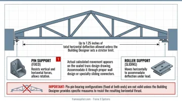
Actual calculated movement appears on the sealed truss design drawing. Accommodate it through proper wall design or specialty sliding connectors.
Important: Pin-pin bearing configurations (fixed at both ends) are not valid unless the Building Designer provides specific measures to resist the resulting horizontal thrust.
Material Specifications
Wood Trusses:
- Chord sizes are specified on the truss design drawing based on span, loads, and engineering analysis
- All lumber must meet species, grade, and quality standards specified in the sealed drawings
- Metal plate connectors must comply with TPI 1 requirements
Cold-Formed Steel Trusses:
- Member sizes, gauges, and grades must match the sealed design drawings
- Connections and fasteners must comply with AISI S100 requirements
- Serviceability limits depend on intended function and realistic load combinations
Connection and Fastening Requirements
The truss design drawing must specify:
- Joint connectors and truss-to-girder connections
- Uplift connectors sized for wind loads
- Fastener types, sizes, and installation requirements
Specialty connectors such as Simpson's TC TrussConnect are designed specifically for scissor trusses, accommodating up to 1.25 inches of horizontal movement while providing an uplift connection. These connectors allow the truss to move at the roller bearing while maintaining lateral support and code-required uplift resistance.
What to Consider When Designing Scissor Trusses
Designing scissor trusses means balancing ceiling aesthetics and interior volume against span capacity, load resistance, budget, and install timeline. These six factors keep that tradeoff clear from first layout through sealed drawings.
Factor 1: Span and Ceiling Height Requirements
The required clear span and desired interior ceiling height are the starting points for scissor truss design. Longer spans require deeper truss profiles and stronger materials, while ceiling height depends on the bottom chord pitch (scissor angle) in relation to the roof pitch.
Verify the span and height against both structural codes and the architectural intent before locking geometry. The sealed truss design drawing should list span, slope/depth, bearing widths, reactions, and member sizes for the specific project.
Factor 2: Roof Pitch and Bottom Chord Pitch
Roof pitch (the slope of the top chords) affects snow load accumulation, roofing material options, and overall truss geometry. The bottom chord pitch creates the vaulted ceiling and influences truss depth, web member configuration, and horizontal deflection.
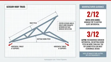
Manufacturer Guidance:
- MiTek (2010 guide): Requires a top-to-bottom slope differential of at least 2/12
- Alpine: Recommends at least 3/12 differential, or a bottom chord pitch no more than half the top chord pitch, as most economical
These are manufacturer criteria, not code requirements. The relationship between roof pitch and bottom chord pitch influences horizontal thrust at supports—steeper scissor angles create more dramatic interiors but may increase deflection.
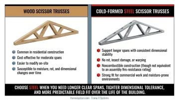
Factor 3: Material Selection (Wood vs. Steel)
Wood Scissor Trusses:
- Common in residential construction
- Cost-effective for moderate spans
- Easier to modify on-site
- Susceptible to moisture, rot, and dimensional changes over time
Cold-Formed Steel Scissor Trusses:
- Support longer spans with consistent dimensional stability
- No rot, insect damage, or warping
- Noncombustible construction (though not equivalent to an assembly fire-resistance rating)
- Strong fit for commercial work and moisture-prone environments
Choose steel when you need longer clear spans, tighter dimensional tolerance, and more predictable field fit over the life of the building.
Factor 4: Load Conditions and Engineering Specifications
Accurate load definition is essential for safe, code-compliant scissor truss design. Required loads include:
- Dead loads — roofing, insulation, drywall, mechanical equipment
- Live loads — snow accumulation based on local climate zones, maintenance access
- Wind loads — uplift forces, lateral pressures, exposure category
Engineered designs must meet local building codes and include stamped drawings from licensed professionals. Use the ASCE Hazard Tool for location-specific wind and snow data, then confirm risk category, site conditions, and local amendments with the project engineer.
Factor 5: Bearing Conditions and Horizontal Deflection
The standard pin-roller bearing configuration allows one end to slide horizontally to accommodate deflection under load. Horizontal deflection depends on span, loads, and truss geometry, and the calculated value appears on the sealed truss design drawing.
According to Simpson Strong-Tie's interpretation of TPI standards, up to 1.25 inches of total horizontal movement is permitted absent a stricter Building Designer limit. Designs that exceed this amount may require special lateral-movement provisions.
This movement must be accommodated through:
- Proper wall design (allowing horizontal movement without damage)
- Specialty sliding connectors (such as Simpson's TC TrussConnect)
- Coordination with finishes and attached building systems
Failure to accommodate horizontal deflection can result in cracked walls, damaged finishes, or structural distress.
Factor 6: Integration with Building Systems
Scissor trusses create a tapered attic space at the eaves, which presents challenges for insulation, ventilation, HVAC, and electrical installations.
Code-Required Insulation and Ventilation:
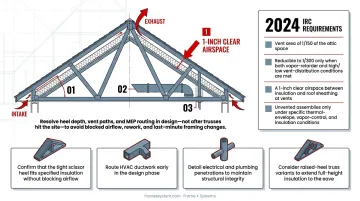
The 2024 IRC requires:
- Vent area of 1/150 of the attic space
- Reducible to 1/300 only when both vapor-retarder and high/low vent-distribution conditions are met
- A 1-inch clear airspace between insulation and roof sheathing at vents
- Unvented assemblies only under specific thermal-envelope, vapor-control, and insulation conditions
Coordination Checklist:
- Confirm that the tight scissor heel fits specified insulation without blocking airflow
- Route HVAC ductwork early in the design phase
- Detail electrical and plumbing penetrations to maintain structural integrity
- Consider raised-heel truss variants to extend full-height insulation to the eave
Resolve heel depth, vent paths, and MEP routing in design—not after trusses hit the site—to avoid blocked airflow, rework, and last-minute framing changes.
How Frame X Systems Can Help
Frame X Systems is an architect-led manufacturing partner specializing in cold-formed steel framing solutions, including engineered roof and floor trusses—and scissor trusses for vaulted ceilings. With 28+ years of construction experience and 150+ projects designed, FrameX resolves constructability challenges before construction begins through BIM coordination and design collaboration.
Installation-Ready Cold-Formed Steel Truss Systems
FrameX delivers complete truss systems with:
- Complete engineering: project-specific structural analysis and sealed stamped drawings
- BIM coordination models: 3D clash detection and system integration before fabrication
- Precision manufacturing: dimensional consistency and predictable field fit
- Sequenced delivery: labeled, bundled panels optimized for construction workflow
- National delivery capability: serving projects across the United States
Advantages Over Site-Built Alternatives
- Longer clear spans with consistent structural performance
- Resistance to moisture, rot, warping, and decay
- Faster installation with reduced on-site labor
- Galvanized cold-formed steel construction with noncombustible properties
- Reduced RFIs, change orders, and field modifications
Collaborative Design-Assist Process
FrameX works alongside architects, engineers, contractors, and developers to:
- Integrate truss design with overall building systems during preconstruction
- Identify and resolve design conflicts through BIM coordination
- Optimize framing approach for performance, cost-effectiveness, and constructability
- Provide comprehensive support from design through installation
On scissor truss projects—vaulted ceilings, long clear spans, or complex roof geometry—FrameX pairs design-assist and BIM coordination with a stamped, installation-ready package so the system fits the architecture and the jobsite sequence.
Conclusion
Successful scissor truss design requires balancing architectural vision with structural realities and practical constraints. Vaulted ceilings and open interiors must still meet span limits, load requirements, and deflection limits while staying aligned with budget, installation complexity, and building-system coordination.
What matters is selecting the right truss configuration, materials, and engineering approach for the project's requirements and site conditions.
Early collaboration matters. Engaging truss manufacturers, structural engineers, and specialty fabricators like Frame X Systems during preconstruction helps optimize scissor truss designs for performance, cost, and constructability.
Before construction begins, coordinate:
- Bearing conditions
- Horizontal deflection
- Insulation and ventilation strategy
- Building-system integration
That upfront work prevents costly field modifications and supports a successful installation.
Frequently Asked Questions
What is a scissor truss roof?
A scissor truss roof uses trusses with angled bottom chords that slope upward to create a vaulted or cathedral ceiling effect, combining roof structure and ceiling framing in a single engineered system.
What is the purpose of a scissor truss?
The primary purpose is to provide both roof structural support and a vaulted ceiling, eliminating the need for separate ceiling joists while creating more interior volume and natural light potential.
How do scissor trusses differ from regular trusses?
Regular trusses have flat, horizontal bottom chords that create flat ceilings and accessible attic space, while scissor trusses have angled bottom chords that slope upward to form vaulted ceilings with reduced attic access.
How far can a scissor truss span?
Scissor truss spans are set through project-specific structural engineering, sealed drawings, and code compliance. Capacity depends on materials, roof and bottom-chord pitch, loads, and bearing design. Custom spans can reach 80 feet with specialized engineering; typical residential spans vary by project.
What is the recommended spacing for scissor trusses?
Truss spacing is specified on the sealed design drawing and varies with span, loads, and engineering. There is no universal code default for scissor trusses. Spacing comes from project-specific analysis.
How much do scissor trusses cost?
Costs vary by span, materials, design complexity, loads, and region. Request project-specific quotes from the sealed truss design drawing. Higher material cost is partly offset because separate ceiling framing is not required.