Introduction to Cold-Formed Steel Column Design
Multi-story residential and commercial buildings face a persistent challenge: supporting cumulative gravity loads across multiple floors while controlling cost, construction time, and material handling on crowded jobsites. Traditional structural systems often require heavy equipment, extended schedules, and complex field coordination.
Cold-formed steel (CFS) columns address these pain points directly. Formed from sheet steel rolled into C-sections, tracks, or built-up shapes at room temperature, they deliver high strength in a lightweight, dimensionally consistent package.
According to the Steel Framing Industry Association, total U.S. CFS manufacturing volume increased 1.7% year-over-year in Q1 2025. That growth reflects continued adoption across residential, commercial, and mixed-use projects.
This article covers CFS column properties, the AISI S100 design process, load and buckling checks, connection detailing, and coordination strategies that resolve constructability issues before fabrication begins.
Key Takeaways
- CFS columns deliver 33–50 ksi yield strength at light weight for multi-story load-bearing walls and isolated columns
- Address local, distortional, and global buckling with effective-width methods under AISI S100
- Coordinate base plates and beam-to-column bearing before fabrication to prevent field rework
- Use BIM and preconstruction collaboration to optimize member sizing and confirm capacity early
Understanding Cold-Formed Steel Columns: Material Properties and Applications
Cold-formed steel columns are vertical load-bearing members made from sheet steel rolled into C-sections, tracks, or specialized shapes without heat. Unlike hot-rolled steel formed at elevated temperatures, CFS is roll-formed at room temperature, which preserves dimensional accuracy and consistent material properties.
Material properties:
- Yield strength: 33 ksi for thinner gauges (33 and 43 mil), 50 ksi for structural-grade members (54, 68, and 97 mil)
- Galvanization: G60 (0.60 oz/ft² total zinc coating) is common, with CP60, CP90, and G90 options available
- Dimensional stability: Uniform cross-sections with tight tolerances reduce field adjustment
Typical applications include:
- Load-bearing walls in multi-story buildings (residential, commercial, mixed-use)
- Jamb assemblies at stacked door and window openings
- Isolated columns in open floor plans
- Podium-to-superstructure transitions in wood-over-podium construction
CFS vs. hot-rolled steel columns: CFS is lighter, easier to handle on-site, and more cost-effective for moderate axial loads. However, thin-walled sections require different design approaches due to local and distortional buckling susceptibility. Hot-rolled steel remains the preferred choice for very heavy loads or high-rise primary framing.
Common CFS Column Member Types
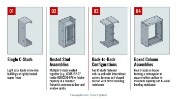
- Single C-studs: Light axial loads in low-rise buildings or lightly loaded upper floors
- Nested stud assemblies: Multiple C-studs nested together (e.g., 600S162-97 inside 600S200-97) for higher capacity in a compact footprint; common at door and window jambs
- Back-to-back configurations: Two C-studs fastened web-to-web with intermittent screws, forming an I-shaped section with better buckling resistance
- Boxed column assemblies: Four C-studs or tracks forming a rectangular or square hollow section for maximum capacity and bi-axial bending resistance
Applicable Design Codes and Standards
The primary design standard is AISI S100, North American Specification for the Design of Cold-Formed Steel Structural Members. The current edition, ANSI/SDI AISI S100-24, is available free from the Steel Deck Institute. However, the 2024 International Building Code (IBC) references AISI S100-16 (2020) with S2-20, so always design to the edition adopted by your jurisdiction.
Key code references:
- IBC Chapter 5: Controls building height, area, and construction type
- IBC Chapter 16: Directs structural design requirements and load combinations to ASCE 7
- IBC Chapter 22: Adopts AISI S100 for CFS member design
- Fire ratings (IBC Table 601): 3-hour, 2-hour, 1-hour, or 0-hour by construction type (IA through IIB)
Fire resistance is assembly-based. Select a tested UL-listed assembly that matches your member sizes, spacing, and protection materials.
Load Types and Design Considerations for CFS Columns
Column Load Types
- Concentric axial compression: Load applied through the member's centroid—the primary load case for most columns. Design per AISI S100 Section C4.
- Eccentric loads: Loads offset from the centroid create bending moments plus axial force. Common when beams frame into one flange or wall openings shift the load path.
- Combined axial plus bending: Wind or seismic forces add bending moments. Use AISI S100 Section C5 interaction equations to confirm the member resists both actions at once.
Gravity Load Accumulation in Multi-Story Buildings
Columns must support cumulative dead loads (framing, cladding, floors, roofing) and live loads (occupancy, snow) from all stories above. Each floor adds to the total factored load, so bottom-story columns carry the highest demand.
Use ASCE 7 load combinations for strength design. Verify the exact combinations in the ASCE 7 edition adopted by your jurisdiction. Typical combinations cover dead, live, snow, roof live, and wind or seismic loads.
Critical Buckling Modes for CFS Columns
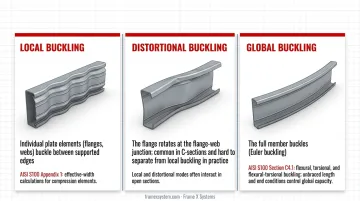
Thin-walled CFS sections are susceptible to three buckling modes. Design must address all of them:
- Local buckling: Individual plate elements (flanges, webs) buckle between supported edges. AISI S100 Appendix 1 uses effective-width calculations for compression elements.
- Distortional buckling: The flange rotates at the flange-web junction. This mode is common in C-sections and hard to separate from local buckling in practice. Local and distortional modes often interact in open sections.
- Global buckling: The full member buckles (Euler buckling). AISI S100 Section C4.1 covers flexural, torsional, and flexural-torsional buckling. Unbraced length and end conditions control global capacity.
Lateral-Torsional Stability Requirements
CFS columns need bracing at regular intervals to prevent out-of-plane buckling. Typical brace points include:
- Floor-level tracks
- Blocking
- Sheathing attachment
Spacing between braced points sets the unbraced length used in capacity calculations. Confirm bracing has the strength and stiffness needed to support the assumed effective length.
Effective Length Factors
- Unbraced length: Distance between points of lateral restraint.
- K-factor: Accounts for end fixity:
- Pinned-pinned: K = 1.0
- Fixed-pinned: K ≈ 0.7
- Fixed-fixed: K approaches 0.5
Do not assume K = 1.0 without analysis. End conditions change capacity significantly.
Step-by-Step Design Process for Cold-Formed Steel Columns
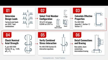
Work through loads, trial section, strength checks, and detailing in this order when designing cold-formed steel columns to AISI S100 and ASCE 7.
Step 1 – Determine design loads
Calculate factored axial loads using ASCE 7 load combinations adopted by your jurisdiction. Include accumulation from all supported floors and roof. Identify any eccentric loading or moment conditions from beam connections or wall offsets.
Step 2 – Select trial member configuration
Choose an initial column section based on load magnitude:
- Light loads: Single C-stud
- Moderate loads: Nested or back-to-back studs
- Heavy loads: Boxed assemblies
Typical structural gauges are 33, 43, 54, 68, and 97 mil. Design thicknesses are 0.0346, 0.0451, 0.0566, 0.0713, and 0.1017 in., respectively, with minimum thickness at 95% of design.
Step 3 – Calculate effective properties
Determine the effective width of compression elements per AISI S100 Appendix 1, accounting for local buckling. Section 1.2 covers unstiffened elements. Calculate effective section properties: area, moment of inertia, and section modulus.
Step 4 – Check nominal axial strength
Calculate nominal axial strength (Pn) for flexural, torsional, and torsional-flexural buckling per AISI S100 Section C4. For LRFD, apply the resistance factor φc = 0.85 and verify that φPn ≥ Pu (required factored axial strength).
Step 5 – Verify combined stress interaction
If bending moments are present, check the combined axial and bending interaction equations per AISI S100 Section C5.
Step 6 – Detail connections and bracing
Design base plate connections to transfer column loads to the foundation, beam-to-column connections for supported framing, and intermediate bracing to maintain the assumed effective length. Connection design is covered in detail below.
Built-Up Column Configurations
When a single stud is not enough, built-up assemblies increase capacity beyond the trial options in Step 2:
- Nested studs: Stack multiple C-studs inside one another for higher load capacity in a compact section; well suited to jamb columns at aligned door and window openings
- Back-to-back: Connect two C-studs web-to-web with intermittent screws or continuous track to form an I-shaped section. Space connectors per AISI S100 Section D1.2 (two-shape built-ups; not D1.3). Modified slenderness accounts for connector spacing and limits it relative to governing slenderness
- Boxed assemblies: Four C-studs or tracks form a rectangular or square hollow section for maximum capacity and bi-axial bending resistance on isolated columns or heavy concentrated loads
Connection Design and Practical Detailing Considerations
Column Base Plate Connections
Steel bearing plates distribute column loads to concrete foundations or podium slabs. Size the plate to limit bearing stress per the ACI 318 edition adopted by your jurisdiction.
Use cast-in-place anchor bolts or post-installed anchors (wedge anchors, epoxy anchors) to resist uplift and lateral forces. Verify anchor capacity against the manufacturer's evaluation report and the adopted ACI 318 provisions.
Beam-to-Column Connections
Clip angles, seat plates, or proprietary connectors transfer floor and roof loads to columns. The connection must develop the full required capacity and accommodate erection tolerances. Use manufacturer load tables and fastener schedules. Connection capacity is configuration-specific and cannot be assumed.
Jamb Stack Detailing in Multi-Story Buildings
When door or window openings align vertically, jamb columns accumulate significant loads from each floor above. Use nested stud configurations to increase capacity within a narrow jamb width.
Install top-track load distribution members with steel stiffener plates at each floor level. At podium transitions, coordinate embed plates or bearing conditions early so load transfer stays continuous.
Fastener Requirements
Steel-to-steel connections typically use self-drilling screws. Per AISI S100 Section J4:
- Nominal diameters: 0.08 to 0.25 in.
- Minimum center spacing: 3d (three times nominal diameter)
- Minimum edge distance: 1.5d
Match screw size, point type, head style, and corrosion protection to the connection schedule and load requirements.
For sheathing attachment, pneumatic pins or screws are common. Follow manufacturer spacing and edge-distance requirements.
Preconstruction Coordination
Engage a CFS design partner early so connection details are resolved before fabrication, not in the field. Frame X Systems provides architect-led design assist and BIM coordination built around that goal.
Preconstruction deliverables typically include:
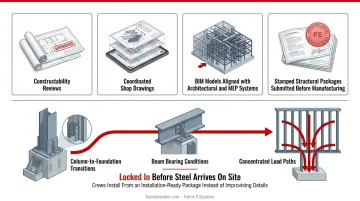
- Constructability reviews
- Coordinated shop drawings
- BIM models aligned with architectural and MEP systems
- Stamped structural packages submitted before manufacturing
That coordination cuts RFIs and field fabrication errors. Column-to-foundation transitions, beam bearing conditions, and concentrated load paths get locked in before steel arrives on site—so crews install from an installation-ready package instead of improvising details.
Design Software, Tools, and Common Challenges
Available Design Software
Common tools for CFS column work include:
- RISA: Supports CFS shape properties using AISI or manufacturer values; confirm edition and design scope
- Simpson Strong-Tie CFS Designer: Designs CFS beam-column members to AISI specifications; check edition limits on the vendor site
- SAP2000: Includes interactive CFS frame-design results; verify the supported AISI edition before automated checks
Software verification is critical. Confirm your tool uses the AISI S100 edition adopted by your jurisdiction—model and analysis capability does not automatically mean code-check compliance.
How BIM Coordination Improves Outcomes
3D BIM models flag column-foundation conflicts, beam bearing interferences, and MEP clashes before fabrication. Frame X Systems delivers coordinated BIM models with every project, aligning CFS framing with architectural, structural, and MEP systems.
That workflow supports optimized layouts, accurate shop drawings, and installation-ready systems. On one documented three-story, 64,000 ft² CFS project, BIM-supported panel prefabrication cut two months from the schedule.
Common Design Challenges
- Concentrated loads at beam bearings: Slender CFS webs can buckle at interior or end supports. Web crippling is a required limit-state check. Use bearing stiffeners (C-section, track-section, clip angles, or proprietary) when unstiffened web-crippling strength is inadequate.
- Stacked openings / high-load jamb columns: Check the full jamb/header load path. Use nested configurations with load-distribution tracks at each floor. Do not multiply a single-stud table value without accounting for built-up behavior and connector spacing.
- Maintaining fire ratings: Select a UL-tested assembly that matches member sizes, spacing, board layers, insulation, fasteners, and protection details. The CFSEI Fire & Acoustic Design Guide indexes UL and other listings, but the testing-agency listing controls. Do not design from the summary alone.
Frequently Asked Questions
What is cold-formed steel?
Cold-formed steel is structural-quality sheet steel formed into shapes (C-sections, tracks, angles) at room temperature through roll-forming. This process produces lightweight, high-strength framing members with uniform quality and tight dimensional tolerances.
How strong is cold-formed steel?
Cold-formed steel typically has yield strengths of 33 ksi to 50 ksi, comparable to or exceeding hot-rolled A36 steel (36 ksi). That strength-to-weight ratio lets properly designed CFS columns—including built-up sections—support substantial loads, often 50+ kips in multi-story work.
Is there a code for cold-formed steel?
Yes. AISI S100, North American Specification for the Design of Cold-Formed Steel Structural Members, is the primary design standard, adopted into the International Building Code (IBC). It covers column design, effective width, built-up members, and connections used in CFS framing.
What are the common failure modes for cold-formed steel columns?
CFS columns can fail by local buckling, distortional buckling, global buckling, or connection failure. AISI S100 design checks effective width, slenderness, and member capacity so each mode is accounted for.
How do you connect cold-formed steel columns to foundations?
Columns connect via steel base plates bolted to concrete with cast-in-place anchor bolts or post-installed anchors (wedge anchors, epoxy anchors). Size the plate for bearing stress limits and lay out bolts for tension and shear per ACI 318 and the anchor evaluation reports.
Can cold-formed steel columns support multiple stories?
Yes. CFS columns are widely used in multi-story buildings up to 8-10 stories. Built-up configurations (nested studs, boxed assemblies) plus floor-level bracing let columns carry cumulative gravity loads within IBC height and construction-type limits.