Introduction
Picture this: an architect opens Revit on Monday morning to model a four-story multifamily building with cold-formed steel framing. By noon, they're still manually sketching studs, tracks, headers, and connections—each custom piece checked against AISI standards and constructability requirements.
By Friday, the framing model is still incomplete, and the MEP team is waiting.
Cold-Formed Steel (CFS) BIM families eliminate that bottleneck. These parametric, pre-built Revit components replace manual modeling with ready-to-place geometry. They cut documentation time and carry the material properties, connection details, and fabrication data architects, engineers, and contractors need from design through manufacturing.
This guide covers what CFS BIM families include, how to judge quality, and how manufacturer-provided families improve coordination across the project team.
Key Takeaways
- Parametric CFS families replace custom Revit modeling with standards-ready framing components
- Manufacturer-provided families cut modeling time and reduce geometry and data errors
- Quality families support clash detection, fabrication exports, and multi-trade coordination
- Strong families pair accurate geometry with AISI material data and the right LOD per phase
What Are Cold-Formed Steel BIM Families?
BIM families are reusable, parametric building components in Revit that contain both geometric and non-geometric data. Think of them as intelligent digital objects: a stud family "knows" its section profile, gauge thickness, material grade, and structural properties—not just its 3D shape.
CFS BIM families differ from generic structural framing families. Where a generic framing member might store only length and a basic profile, a cold-formed steel family includes:
- Steel-specific section profiles (C-sections, track sections, U-channels) matching AISI designators
- Gauge thickness and material grade (such as 18-gauge 50 ksi yield strength)
- Connection details such as clip locations, fastener spacing, and hold-down requirements
- Fabrication data including minimum steel thickness, coating designators, and roll-former specifications
Anatomy of a CFS BIM Family
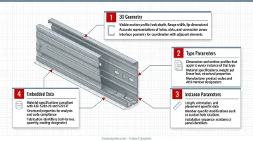
Every properly structured family contains multiple layers of information:
3D Geometry:
- Visible section profile (web depth, flange width, lip dimensions)
- Accurate representations of holes, slots, and connection zones
- Interface geometry for coordination with adjacent elements
Type Parameters:
- Dimensions and section profiles that apply to every instance of that type
- Material specifications, weight per linear foot, structural properties
- Manufacturer product codes and AISI member designators
Instance Parameters:
- Length, orientation, and placement-specific data
- Member-specific modifications such as custom hole locations
- Installation sequence numbers or panel identifiers
Embedded Data:
- Material specifications compliant with AISI S240-20 and S201-17
- Structural properties for analysis and code compliance
- Fabrication identifiers (roll-former, quantity, coating designator)
System Families vs. Loadable Families
Revit organizes families into two categories relevant to CFS framing:
- System families (walls, floors, roofs) are built into Revit and modified through type properties; you cannot save them as standalone .rfa files
- Loadable families (studs, tracks, bridging, clips, connections) are external .rfa files you load into projects; manufacturers typically distribute CFS content as loadable families
For cold-formed steel work, most framing members (studs, joists, headers, bridging, and connection hardware) arrive as loadable families. Wall panel assemblies may combine system families (the wall type) with embedded loadable families (the framing members).
Level of Development (LOD) Requirements
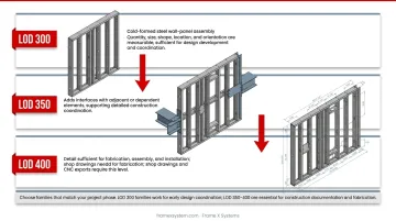
The BIMForum LOD Specification defines how much detail a model element must contain:
- LOD 300: Quantity, size, shape, location, and orientation are measurable—sufficient for design development and coordination
- LOD 350: Adds interfaces with adjacent or dependent elements, supporting detailed construction coordination
- LOD 400: Detail sufficient for fabrication, assembly, and installation; shop drawings and CNC exports require this level
Choose families that match your project phase. LOD 300 families work for early design coordination; LOD 350-400 are essential for construction documentation and fabrication.
Why Use CFS BIM Families in Revit?
Time Efficiency
Project-specific evidence shows real time gains from structured CFS BIM workflows. A BuildSteel case study covered a 64,000-square-foot, 73-bedroom, three-story project.
The BIM modeler built the cold-formed steel framing model and eliminated all RFIs. Coordinated prefabricated panels then cut two months from the construction schedule.
Another BuildSteel example involved 750 prefabricated 15-foot panels and reported "substantial labor savings," though it did not publish specific percentages.
Properly structured families speed modeling and documentation. How much you gain still depends on project complexity, team coordination, and fabrication workflows.
Accuracy and Consistency
Pre-built families eliminate dimensional errors and ensure all team members use standardized components. When every architect, engineer, and detailer places the same manufacturer family for a 600S162-54 stud, dimensions stay consistent. You avoid failures like one person modeling a 6-inch stud while another assumes 5.5 inches.
Families with embedded AISI data also prevent specification errors. A family encoded with the correct member designator, minimum thickness, yield strength, and coating designator reduces the risk that fabricators receive ambiguous or conflicting information.
Coordination Benefits
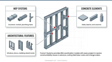
Accurate geometry enables clash detection before construction begins. When your CFS wall families include precise stud spacing, track dimensions, and connection-zone geometry, Revit's clash-detection tools can identify conflicts with:
- MEP systems (ductwork, conduit, plumbing risers)
- Concrete elements (slabs, beams, columns)
- Architectural features (windows, doors, cladding attachments)
Frame X Systems provides BIM coordination models with every project to resolve constructability issues in advance, cutting field labor costs and change orders. These models align cold-formed steel framing with architectural, structural, and MEP systems so clashes surface before fabrication.
Fabrication Readiness
Properly structured families can export directly to fabrication software when they contain manufacturer-specific data. However, fabrication readiness is not guaranteed by geometry alone. BIMForum LOD 400 requires detail sufficient for fabrication, assembly, and installation, but CFS software vendors describe separate machine-readable exports for light-gauge steel machinery.
To ensure fabrication readiness:
- Verify families include AISI S240-20 fields (member designator, minimum thickness, yield strength, coating designator)
- Confirm your fabricator's workflow and required file formats
- Test export compatibility with your roll-forming equipment or third-party plugins
Cost Control
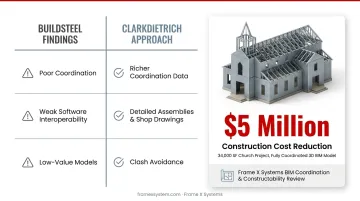
BuildSteel research flags poor coordination, weak software interoperability, and low-value models as conditions that make BIM costly or counterproductive.
ClarkDietrich, by contrast, notes that its Revit tools import CFS products with richer coordination data. Those tools support detailed assemblies, documentation, shop drawings, and clash avoidance.
Frame X Systems' architect-led design assist and BIM coordination workflow supports constructability reviews before fabrication, reducing RFIs, change orders, and field labor. In one documented case, a 34,000-square-foot church project, a fully coordinated 3D BIM model and contractor-friendly construction documents contributed to a $5 million construction-cost reduction.
Types and Sources of CFS BIM Families
Types of Families by Component Category
Framing Members:
- Studs (C-sections, track sections, U-channels)
- Joists, headers, sills
- Bridging and lateral bracing
Connection Components:
- Clips, plates, angles
- Fasteners, hold-downs, straps
- Bearing plates and reinforcement hardware
Assemblies:
- Pre-built wall panel families with studs, tracks, and sheathing
- Floor cassette families with joists and rim tracks
- Truss families with all chord and web members included
Sources for Obtaining CFS Families
Manufacturer Libraries:
| Manufacturer | Verified Offer | URL |
|---|---|---|
| ClarkDietrich | Free Revit families for ProSTUD, RedHeader, MaxTrak, clips, and wall assemblies | ClarkDietrich BIM Systems |
| CEMCO | Revit files via ARCAT for walls, floors, headers, shaftwall, and related details | CEMCO Typical Details & Revit Files |
| The Steel Network | Light-steel framing design resources, including BIM objects | TSN BIM Objects |
BIM Content Platforms:
- BIMsmith Market: ClarkDietrich families and CEMCO manufacturer pages with supporting product data
- BIMobject: ClarkDietrich MaxTrak and ProSTUD objects available for download
- NBS Source: 9 free cold-formed galvanized steel BIM objects (UK catalog; verify U.S. product and code applicability)
Industry Organizations:
The Steel Framing Industry Association (SFIA) publishes design guides and tables for CFS members—section properties, wall heights, load/span data, headers, and web crippling—plus notes on nonstructural stud limiting heights. These are technical references, not Revit family libraries.
Quality Considerations When Selecting Families
Evaluate families against these criteria:
- Verify web depth, flange width, designation thickness, and member type match AISI S240-20 designators
- Match LOD to phase: LOD 300 for design coordination; LOD 350–400 for construction and fabrication
- Confirm embedded grade, yield strength, coating designator, and minimum steel thickness
- Test that key fields appear in schedules and tags—family-only parameters need shared parameters
Warnings:
Skip generic structural framing families that lack CFS-specific data. A rectangular-tube family can look right in 3D and still fail fabrication, takeoffs, and code documentation.
Before you standardize on a library:
- Verify the publisher and product line
- Test families in a staging project
- Confirm the set matches your fabricator’s requirements
How to Use CFS BIM Families in Your Workflow
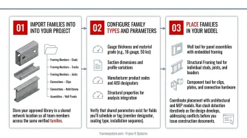
Step 1: Import Families into Your Project
Use Revit's "Load Family" command to import .rfa files. Organize them in a project library structure by category:
- Framing Members > Studs
- Framing Members > Tracks
- Framing Members > Joists
- Connections > Clips
- Connections > Hold-Downs
- Assemblies > Wall Panels
Store your approved library in a shared network location so all team members access the same verified families.
Step 2: Configure Family Types and Parameters
Before placing families, configure type properties to match your project specifications:
- Gauge thickness and material grade (e.g., 18-gauge, 50 ksi)
- Section dimensions and profile variations
- Manufacturer product codes and AISI designators
- Structural properties for analysis integration
Verify that shared parameters exist for fields you'll schedule or tag (member designator, coating type, installation sequence).
Step 3: Place Families in Your Model
Use appropriate Revit tools based on family type:
- Wall tool for panel assemblies with embedded framing
- Structural Framing tool for individual studs, joists, and headers
- Component tool for clips, plates, and connection hardware
Coordinate placement with architectural and MEP models. Run clash detection iteratively as the design develops, addressing conflicts before you issue construction documents.
Best Practices and Common Pitfalls
Create and Maintain a Standardized Family Library
Build a verified family library organized by category, manufacturer, and product series. Require every team member—architects, engineers, detailers, and contractors—to use the same components. Version-control the library, audit families against current AISI standards, and retire outdated or low-quality content.
Test representative arrays of studs, tracks, joists, clips, and headers in a staging model before release. Confirm that:
- Parameters populate schedules correctly
- Geometry coordinates cleanly with adjacent elements
- File performance stays acceptable in production models
Avoid Over-Modeling
Excessive detail creates file bloat and slows performance. Autodesk recommends cutting the amount and size of imported third-party CAD geometry inside families. Use 2D symbolic lines for complex 3D shapes so Revit does not recalculate heavy projections in every model view.
For CFS families, model only the detail your LOD requires:
- LOD 300: Section profile, basic connection zones, no fastener heads
- LOD 350: Interface geometry, connection-plate outlines, major penetrations
- LOD 400: Fabrication-level geometry, but omit micro-detail (individual screw threads, washer chamfers) unless your fabricator requires it
Be Cautious Using Families from Untrusted Sources
Poorly constructed families contain errors, missing data, or incorrect geometry that create problems downstream. Common issues include:
- Incorrect AISI designators or missing material grades
- Non-schedulable parameters that break takeoff workflows
- Geometry that doesn't match published product dimensions
- Excessive file size or nested detail that degrades performance
Always test unfamiliar families on non-critical projects first:
- Validate dimensions against manufacturer product literature
- Confirm parameters populate schedules
- Verify export compatibility with your fabrication workflow
Check Model-vs-Detail Consistency
A BuildSteel case study warns that design models often diverge from how construction models are assembled. In one example, a CFS wall was modeled flush to deck while 2D notes called for it to stop six inches above the ceiling plane.
Coordinate 3D geometry with annotation, confirm interface assumptions with contractors, and resolve conflicts before fabrication.
Frequently Asked Questions
What is the difference between a generic Revit family and a cold-formed steel BIM family?
CFS-specific families include steel section properties, gauge thicknesses, AISI member designators, material grades, and coating specifications that generic structural families lack. They support fabrication workflows, material takeoffs, and code-compliance documentation.
Where can I download free CFS BIM families for Revit?
Download families from manufacturer websites (ClarkDietrich, CEMCO via ARCAT), BIM content platforms (BIMsmith Market, BIMobject), or industry resources like the Steel Framing Industry Association.
Do I need a Revit plugin to use cold-formed steel BIM families?
Basic families work with standard Revit. Plugins like MWF Pro Metal / Strucsoft Metal, ARKANCE Metal Framing, or hsbCAD speed framing by automating wall/floor/roof frames, shop drawings, and CNC exports.
How do I ensure my CFS BIM families are accurate for fabrication?
Verify families include AISI S240-20 fields (member designator, minimum thickness, yield strength, coating designator) and match manufacturer specs. Test export compatibility with your fabricator's software and roll-forming equipment before production.
Can I use architectural BIM models to create steel framing shop drawings?
Architectural models often lack the detail and accuracy required for fabrication and should be used only as reference. Shop drawings require LOD 400 geometry, connection details, fastener schedules, and fabrication-specific data that architectural models typically do not contain.
What level of detail (LOD) should CFS BIM families have for construction?
LOD 350–400 is typically required for construction and fabrication. LOD 350 covers interfaces with adjacent elements; LOD 400 adds connection geometry and fastener locations needed for fabrication and installation.