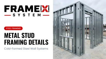
Metal stud framing details encompass all the connection points, fastening methods, spacing requirements, and structural specifications that ensure cold-formed steel framing systems perform as designed. These aren't just lines on a drawing; they're the field-execution instructions that determine whether your walls stand plumb, carry loads safely, and meet code.
This guide covers the essential framing details every architect, contractor, and project manager needs to understand—from basic components and critical connection types to coordination strategies that prevent rework before the first stud goes up.
Key Takeaways
- Track connections, deflection systems, headers, bridging, and fastening specs drive structural performance
- Correct detailing prevents load-transfer failures, acoustic leaks, fire-rating violations, and deflection issues
- Knowing why specs exist helps field teams install correctly and catch problems before they ship
- Pre-construction coordination of framing details cuts RFIs, change orders, and install delays
Understanding Metal Stud Framing Components
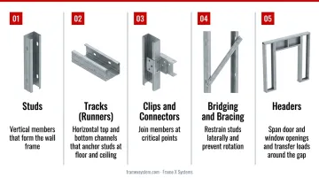
Metal stud framing systems rely on a few primary components working together:
- Studs — vertical members that form the wall frame
- Tracks (runners) — horizontal top and bottom channels that anchor studs at floor and ceiling
- Clips and connectors — join members at critical points
- Bridging and bracing — restrain studs laterally and prevent rotation
- Headers — span door and window openings and transfer loads around the gap
Structural vs. Non-Structural Applications
Structural and non-structural metal framing differ in load path, thickness, and coating:
- Structural framing carries building loads, typically 16-gauge to 18-gauge cold-formed steel with higher strength requirements
- Non-structural framing forms interior partitions, often 20-gauge or 25-gauge, lighter and less expensive
- Coatings: AISI S240-20 requires at least CP60 coating for structural framing within the building envelope; G60 and G90 galvanized coatings are specified based on environmental exposure
Caution: Specifying by gauge alone is risky. A manufacturer's "20-gauge" structural stud may be 33-mil thickness, while a non-structural "20-gauge EQ" product could be just 18-mil. Always specify mil thickness or product designator, not gauge alone.
Sizing Nomenclature
Metal stud sizing follows a specific format: web depth (in hundredths of an inch), type (S = stud, T = track), flange width, and mil thickness.
Example: A stud marked 362S162-54 means:
- 3.62-inch web depth (approximately 3-5/8")
- S = lipped C-shape stud
- 1.62-inch flange width
- 54-mil designation thickness
Common sizes include 3-5/8" and 6" studs, in line with 2×4 and 2×6 wood framing depths. Metal stud sizing reflects web depth, not overall wall thickness. A 3-5/8" stud fits within a wall cavity smaller than 4 inches.
Deflection Track vs. Fixed Track
Fixed track (standard U-channel) rigidly secures stud ends at floor and ceiling, transferring loads and restraining movement.
Deflection track (also called slip track or head-of-wall track) permits vertical structural movement without crushing studs or damaging finishes. Two types exist:
- Deep-leg deflection track: Relies on a designed stud-end gap plus continuous top bridging to allow vertical slip
- Slotted deflection track: Positively attaches studs through vertical slots, guiding controlled movement
Critical difference: With conventional deep-leg track, do NOT screw studs to the track when free slip is required; doing so defeats its purpose. Slotted track like ClarkDietrich MaxTrak requires positive screw attachment at the slot to function correctly.
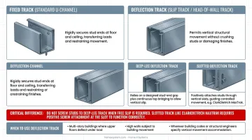
When to use deflection track:
- Multi-story buildings where upper floors deflect under load
- High walls subject to building movement
- Wherever building codes or structural engineers specify vertical movement accommodation
Accessories for Lateral Stability
- Bridging channels (CRC or U-channel): resist stud rotation and minor-axis bending; installed horizontally between studs at specified intervals
- Diagonal bracing: straps or other engineered bracing that restrain distortional buckling and lateral deflection; anchorage points collect brace forces and transfer them to the structure
- Closure channels: cap stud ends or close track openings; not lateral braces unless designed as such
Critical Framing Details & Connections
Stud-to-Track Connections
Stud-to-track connections at floor and ceiling are critical for load transfer and rotational restraint. AISI S240-20 does not prescribe a universal screw count. The connection must be designed or specified in approved drawings.
Common field practice:
- Two screws per stud flange (one each side)
- Minimum edge distance of 1.5× screw diameter
- Center-to-center screw spacing at least 3× screw diameter
- Screws must project at least three exposed threads through the connection
Why it matters: Inadequate fastening allows studs to rotate, shift out-of-plane, or fail to transfer loads properly. That leads to structural inadequacy and potential inspection failures.
Header Details for Openings
Headers span door and window openings, carrying vertical loads and supporting the wall above. Three common configurations:
1. Box beam headers (built-up assemblies):
- Four- or five-piece stud and track members screwed together
- Custom-engineered for each span and load
- Labor-intensive field assembly
2. Back-to-back stud headers:
- Two or more studs joined face-to-face
- Simpler assembly, lower capacity than box beams
- Suitable for lighter loads and shorter spans
3. Track headers:
- Horizontal track members over openings
- Typically used for non-load-bearing or very light loads
- Fast installation but limited structural capacity
Pre-engineered alternatives such as CEMCO ProX headers replace multi-piece built-ups with one- or two-piece factory assemblies and cut field labor. Panelized systems (including Frame X Systems) go further by shipping openings with headers, jambs, and connection patterns already coordinated. Fastener requirements are product-specific: No. 8 or No. 10 sheet-metal screws are typical, but must match the manufacturer's specification.
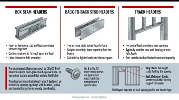
Jamb stud configurations:
- King studs: full-height studs flanking the opening
- Jack (trimmer) studs: shorter studs that directly support the header
- Final layout depends on load, opening width, and header type
Deflection/Slip Track Installations
Deflection track allows vertical structural movement without damaging walls. Proper installation requires:
Gap requirements:
- No universal "1–2 inch" gap: AISI S220-20 requires the architect or engineer to design the stud-to-runner gap
- Product example: ClarkDietrich MaxTrak slotted track allows ±3/4" or ±1" total movement (1.5" and 2" slots)—use only as a product-specific guide
- Size the gap for anticipated deflection from building height, floor span, and loading
Installation rules:
- Do NOT rigidly fasten studs to conventional deep-leg deflection track when free slip is required
- DO positively screw studs to slotted deflection track at the slot guideline
- Install continuous bridging at the top of studs to maintain alignment while allowing vertical slip
Head-of-wall firestopping:
- Fire-rated assemblies must follow the tested UL design exactly
- Firestopping materials and installation methods are assembly-specific
- Do not improvise or substitute materials in listed fire-rated walls
Bridging and Bracing Requirements
Horizontal bridging:
- Installed to restrain stud rotation and minor-axis bending
- Spacing depends on wall height, stud size, and loading (manufacturer tables often assume 4 ft; that is not a code mandate)
- AISI requires designed bracing and effective-length checks, not a blanket mid-height row whenever walls exceed 10 ft
Lateral bracing:
- Attaches studs to structure at specified intervals
- Must be anchored to collect and transfer brace forces
- Track used as an end closure is not automatically a lateral brace
Diagonal strap bracing:
- Used in shear-wall applications to resist lateral forces
- Must be engineered with specified attachment patterns and anchorage points
- Critical for seismic and wind-load resistance
Rim Track, Blocking, and Penetrations
Rim track transfers floor loads from joists to wall studs below. Proper bearing details include:
- Bearing surface aligned with the studs underneath
- Blocking at bearing points to prevent crushing or local buckling
- Coordination with structural loads and engineered drawings
Backing for fixtures:
- Block or back heavy wall-mounted items (cabinets, TVs, grab bars)
- Coordinate locations with finish schedules before drywall
Wood blocking in metal stud walls:
- Allowed only when it complies with the fire-rated assembly
- Do not add unlisted combustible blocking in rated walls; use UL-approved systems only
Penetrations:
- Factory punchouts (AISI S100 / S220-20): centered on the web, ≥24" o.c., no wider than half the web depth or 2.5", no longer than 4.5"
- Larger or relocated openings need engineered reinforcement or patches
- Rated penetrations must match tested firestopping systems
Sizing, Spacing & Code Requirements
Stud size, spacing, and gauge only work when they match load conditions and the governing code path. Treat the values below as common starting points, then confirm them against load tables, listed assemblies, and engineered designs.
Standard Stud Spacing
Common spacing options:
- 16 inches on center (o.c.): Most common for walls, balances material cost and load capacity
- 24 inches o.c.: Used for non-structural partitions or where sheathing and load conditions permit
- 12 inches o.c.: Required for higher load applications or where specified by engineers
Spacing is not arbitrary. It depends on stud size, gauge, wall height, loading conditions, sheathing span capacity, and fire-rating assembly requirements. AISI S240-20 limits certain sheathing-braced structural-wall methods to 24" o.c. maximum, but that is not blanket permission for every wall.
Gauge Selection Criteria
Typical gauge applications:
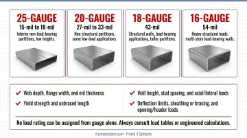
- 25-gauge (15-mil to 18-mil): Interior non-load-bearing partitions, low heights
- 20-gauge (27-mil to 33-mil): Non-structural partitions, some low-load applications
- 18-gauge (43-mil): Structural walls, load-bearing applications, taller partitions
- 16-gauge (54-mil): Heavy structural loads, multi-story load-bearing walls
Selection depends on more than gauge. Review:
- Web depth, flange width, and mil thickness
- Yield strength and unbraced length
- Wall height, stud spacing, and axial/lateral loads
- Deflection limits, sheathing or bracing, and opening/header loads
No load rating can be assigned from gauge alone. Always consult load tables or engineered calculations.
Code Requirements and Standards
Key codes and standards:
- AISI S240-20 (2020): North American Standard for Cold-Formed Steel Structural Framing; governs structural member design, manufacture, installation, and quality
- AISI S220-20 (2020): Covers nonstructural framing, defers typical installation spacing/heights/connections to ASTM C754 and connection strength to AISI S100
- 2024 IBC Section 2206.1: Directs structural CFS floor/roof systems, structural walls, shear/strap-braced walls, diaphragms, and trusses to AISI S240; nonstructural members and connections fall under AISI S220
- UL 263/ASTM E119: Fire-resistance ratings belong to complete listed assemblies. Listed stud size/thickness is a minimum; listed spacing is a maximum
Engineer-stamped designs: Structural applications require stamped designs from a licensed professional engineer. Do not rely on generic details or rules of thumb for load-bearing or critical assemblies.
Tools & Materials for Metal Framing
Essential Installation Tools
Field installation requires:
- Screw guns with depth settings: Control fastener depth to avoid overdrive or underdrive
- Aviation snips (left, right, straight cut): Cut studs, track, and accessories precisely
- Levels and layout tools: Ensure plumb, level, and accurate spacing
- Powder-actuated tools or hammer drills: Attach track to concrete slabs and decks
- Measuring and marking tools: Tape measures, chalk lines, squares
Tool selection is a contractor means-and-methods decision, but tools must not replace proper fastener selection or approved installation instructions.
Fastener Requirements
Connection hardware must match the approved design and applicable AISI and ASTM standards.
Steel-to-steel connections:
- AISI S220-20 requires screws complying with ASTM C1513 or an approved design
- No. 8 or No. 10 self-drilling screws are common; selection is connection-specific
- Screw length must be the greater of 3/4" or sufficient to leave at least three exposed threads through the connection
- Drill point and diameter selected from total connected steel thickness and connector schedule
Track-to-concrete fasteners:
- Powder-actuated fasteners (such as Hilti X-U, X-P) for normal-weight concrete with minimum 3/4" embedment
- Concrete screws (Tapcon-style) as alternative
- Anchor type, spacing, edge distance, substrate strength, and approvals are design-specific. No universal track-anchor spacing applies
Wrong fastener type, size, or spacing compromises connection strength, load transfer, and structural performance. Field substitutions without engineering approval can void warranties and cause failures.
Installation Best Practices & Common Mistakes
Proper Installation Sequence
While AISI standards do not mandate a specific sequence, the following workflow is common contractor practice:
- Install the floor track with straight alignment and proper fastener spacing
- Transfer plumb marks to the ceiling directly above the floor track
- Fasten the ceiling track, leaving a deflection gap if required
- Cut studs to length, accounting for tolerances and bearing gaps
- Install studs at the specified spacing with the correct screw pattern
Common Field Mistakes
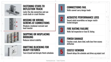
These errors show up repeatedly on metal stud jobs and create expensive downstream problems:
- Fastening studs to deflection track, which locks the slip connection and can crush studs or crack finishes
- Missing screws or using the wrong type or size at connections, which weakens rotational restraint and load transfer
- Skipping bridging rows, spacing them incorrectly, or anchoring them poorly, which reduces lateral stability
- Omitting required blocking for heavy fixtures, which can tear drywall and disrupt finish schedules
When these mistakes slip through, the consequences compound:
- Connections fail and walls cannot carry design loads
- Sound-rated assemblies lose performance when they no longer match tested designs
- Fire-rated walls fail inspection or lose their UL listing
- Finishes crack, doors bind, and walls bow from excess deflection
- Rework delays the schedule and drives up project cost
Field Tips and Trade Coordination
Quality framing depends on habits that catch problems before drywall goes up:
- Use templates for repetitive layouts so stud and opening placement stays accurate
- Mark bridging and blocking locations before drywall so required elements stay visible
- Photograph concealed blocking, bracing, and connections before close-in
- Verify details against drawings at each phase, before corrections get expensive
Coordinate early with other trades:
- Confirm MEP openings are located, sized, and reinforced before rough-in
- Align blocking with finish trades so backing lands where millwork, fixtures, and equipment need it
- Sequence framing, rough-in, inspections, and closeout to avoid trade conflicts
Quality Assurance & Inspection Checkpoints
Staged checkpoints catch metal stud framing issues before walls close. Review materials, installation, and concealed work at each phase below.
Pre-Installation Checkpoints
- Verify material gauge and mil thickness match specifications and approved drawings
- Confirm floor/ceiling tracks are straight and properly fastened at required spacing
- Check for deflection track where specified vs. fixed track where not
- Verify member condition (no damage, corrosion, or deformation)
- Confirm coating/labels meet project requirements
During-Installation Checkpoints
- Verify studs are at specified spacing and properly fastened (no missing screws)
- Confirm bridging is installed at correct intervals and anchored properly
- Check blocking at all specified locations
- Verify plumbness and alignment per ASTM C1007
- Confirm stud end seating and gaps meet design requirements
Pre-Drywall Inspection Points
This is the last chance to verify before walls are closed:
- Verify all connections meet detail requirements (screw count, pattern, edge distance)
- Confirm fire-rated assemblies match UL listings exactly (stud size, spacing, materials)
- Check that all required bracing is in place and properly anchored
- Verify penetrations are properly framed, reinforced, and firestopped
- Confirm photo documentation of concealed work is complete
CFSEI G500-25 (2025) provides a partial field checklist to confirm structural CFS framing follows approved design. Photo documentation is not a universal AISI or IBC requirement, but it is a strong project QA and risk-management practice.
Planning & Coordination for Success
Pre-Construction Coordination
Reviewing framing details with all stakeholders (architect, engineer, contractor, and framers) before installation prevents costly field RFIs and rework. Key benefits include:
- Clarifying connection requirements and detail intent
- Resolving conflicts between framing layout and other trades
- Confirming material specifications and long-lead procurement
- Aligning on inspection hold points and acceptance criteria
Projects that invest in coordination upfront see fewer surprises and faster installation, with stronger quality outcomes.
BIM Coordination in Complex Projects
3D modeling helps identify conflicts before steel is cut:
- Clash detection finds interferences between framing layout and MEP systems
- Verifies blocking locations against finish schedules
- Installation-ready drawings reduce field interpretation errors
- Coordination models support accurate fabrication and sequenced delivery
BuildSteel's 2017 CFS BIM playbook supports model-based review for mid-rise cold-formed steel projects. Collaborative coordination catches conflicts before they reach the field.
Architect-Led Framing Coordination
Architect-led framing coordination connects engineered drawings to field execution. It confirms details are constructible and resolves issues before material is ordered.
Frame X Systems' model treats framing as a coordinated system, not a material-only supply transaction.
Frame X Systems integrates:
- Architect-led design assist and constructability review
- BIM coordination with architectural, structural, and MEP systems
- Project-specific engineered shop drawings and panel layouts
- Stamped structural packages for permitting and compliance
- Precision-manufactured, installation-ready wall panels, trusses, and structural assemblies
- Labeled, bundled, and sequenced delivery aligned with construction workflow
With 28+ years of construction experience and 150+ projects designed, FrameX resolves constructability challenges during preconstruction, reducing RFIs, field labor, change orders, and installation delays. The company manufactures cold-formed steel framing systems in the USA and delivers nationwide.
Frequently Asked Questions
Is metal stud framing cheaper than wood framing?
Material costs are often comparable, but metal can cost less overall thanks to lighter handling, no warping or shrinkage, and less scrap from precision cutting. Total installed cost still depends on labor rates, project complexity, and regional material availability.
What are the typical details of metal stud framing?
Core details cover stud-to-track connections, header assemblies at openings, deflection tracks, bridging and bracing, and blocking for fixtures. Fastening patterns, gaps, spacing, and anchorage are set in the construction documents to meet structural and code requirements.
What are the guidelines for metal stud framing?
Follow AISI S240 for structural framing, AISI S220 for nonstructural framing, the IBC, manufacturer specs, and approved construction documents. Structural work needs engineer-stamped designs, and fire-rated assemblies must match UL listings exactly.
Can metal studs be structural or load-bearing?
Yes. Structural metal studs (typically 16-gauge to 18-gauge, 43-mil to 54-mil) carry significant loads in load-bearing wall applications and are commonly used in multi-story construction. They must be properly specified by a structural engineer based on wall height, spacing, loading, and deflection limits.
What is the standard spacing for metal stud framing?
16 inches on center is most common for walls. 24" o.c. is used for non-structural partitions where sheathing and load conditions permit, and 12" o.c. may be required for higher load applications. Spacing is always specified in the construction documents based on loading, stud capacity, and assembly requirements. It is not chosen arbitrarily in the field.
Are metal studs the same size as 2×4 wood studs?
3-5/8" metal studs are the closest equivalent to 2×4 wood framing (actual 3.5" depth), and 6" metal studs correspond to 2×6 wood framing. However, metal stud sizing reflects web depth, not overall wall thickness, so a 3-5/8" stud produces a thinner wall cavity than wood framing. Do not assume equivalence from nominal depth alone; verify dimensional requirements in the project drawings.